
Communication-in-moving satellite antenna with low profile

A technology of satellite antenna and mobile communication, which is applied in the field of low-profile mobile satellite antenna, which can solve the problems of poor system reliability and low precision of rotation angle, and achieve the effect of large transmission power, improved precision and compact structure

Pending Publication Date: 2018-03-13
SATPRO MEASUREMENT & CONTROL TECH
View PDF0 Cites 9 Cited by
  • Summary
  • Abstract
  • Description
  • Claims
  • Application Information

AI Technical Summary

Problems solved by technology

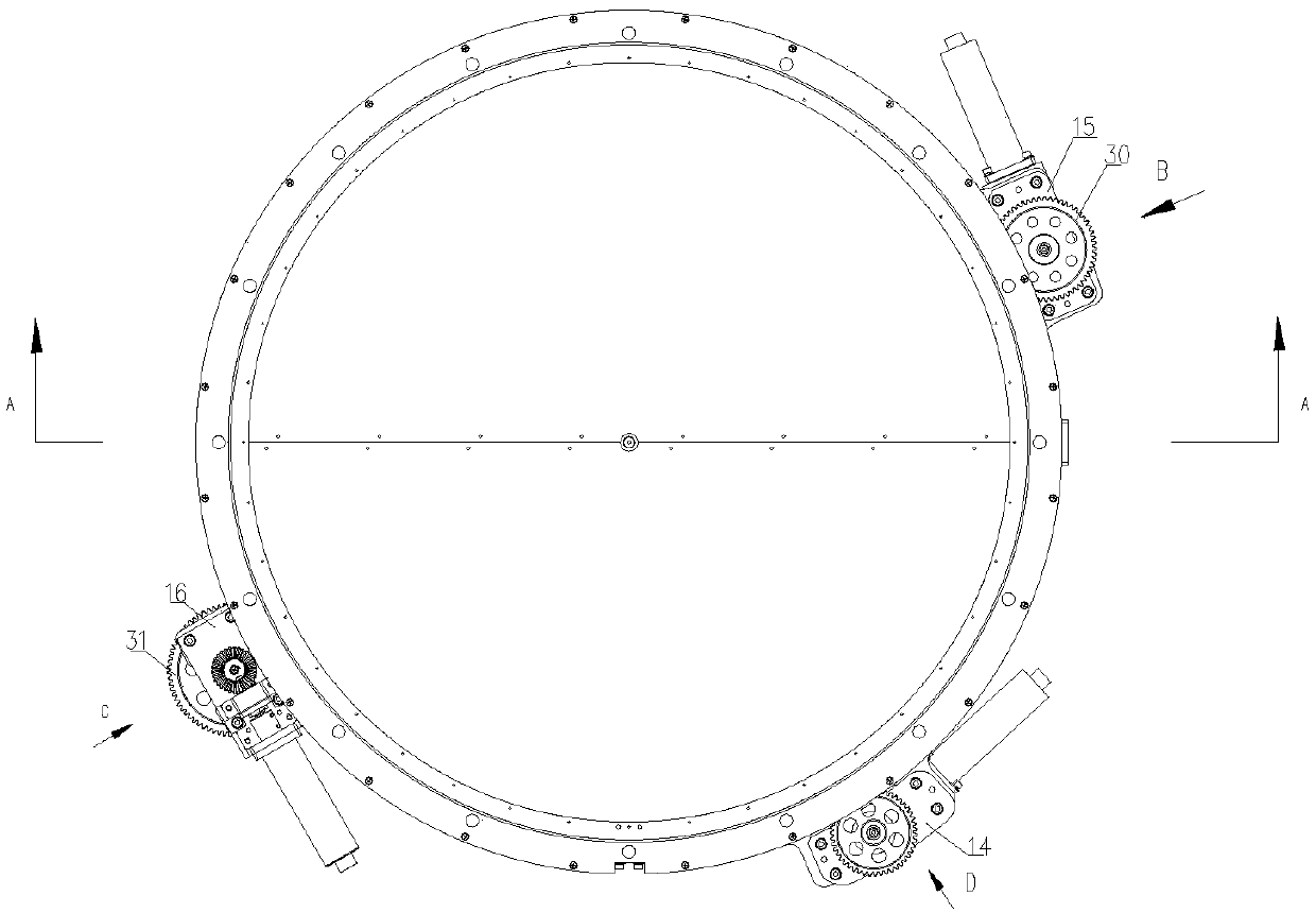
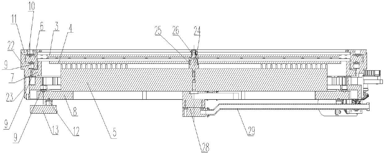
[0005] In order to solve the problems of low rotation angle accuracy and poor system reliability of the phase modulation surface rotation device in the prior art, the present invention provides a low-profile satellite antenna in motion, which realizes rotation through a gear transmission mechanism and improves the rotation angle. accuracy while improving system stability and reliability and reducing satellite antenna profile

Method used


Image

  • Communication-in-moving satellite antenna with low profile
  • Communication-in-moving satellite antenna with low profile
  • Communication-in-moving satellite antenna with low profile

Examples


Embodiment Construction

[0029] In order to further illustrate the technical means and effects adopted by the present invention to achieve the intended purpose, the specific implementation, structural features and effects of the present invention will be described in detail below in conjunction with the accompanying drawings and examples.

[0030] In describing the present invention, it should be understood that the terms "center", "longitudinal", "transverse", "upper", "lower", "front", "rear", "left", "right", The orientations or positional relationships indicated by "vertical", "horizontal", "top", "bottom", "inner", "outer", etc. are based on the orientation or positional relationships shown in the drawings, and are only for the convenience of describing the present invention Creation and simplification of description, rather than indicating or implying that the device or element referred to must have a specific orientation, be constructed and operate in a specific orientation, and therefore should...


PUM


Abstract

The invention relates to a communication-in-moving satellite antenna with a low profile. The communication-in-moving satellite antenna comprises a receiving part and an emission part which are same instructure, wherein the receiving part comprises an upper-layer phase modulation surface, an intermediate-layer phase modulation surface, a lower-layer feeding source surface and a rotation mechanismwhich are sequentially arranged from top to bottom, the rotation mechanism comprises an upper-layer large ring gear, an intermediate-layer large ring gear, a lower-layer large ring gear and a rotationdriving device, and the rotation driving device drives the lower-layer large ring gear, the intermediate-layer large ring gear and the upper-layer large ring gear to rotate so as to achieve rotationof the lower-layer feeding source surface, the intermediate-layer phase modulation surface and the upper-layer phase modulation surface. The beam pitching angle of the satellite antenna is adjusted according to angle difference between the upper-layer phase modulation surface and the intermediate-layer phase modulation surface which are driven by the upper-layer large ring gear and the intermediate-layer large ring gear to rotate, the upper-layer phase modulation surface and the lower-layer phase modulation surface simultaneously rotate, the beam directional angle of the antenna is adjusted according to a rotation angle, the lower-layer feeding source surface is driven to rotate by the lower-layer large ring gear so as to adjust a polarization angle of the satellite antenna, polarization adjustment is achieved, and a main beam of the antenna points to a satellite all the way during the moving process on a vehicle, an airplane and a boat and is maintained within certain accuracy.

Description

technical field [0001] The invention belongs to the technical field of mobile communication satellite antennas, and in particular relates to a low-profile mobile communication satellite antenna. Background technique [0002] At present, most of the high-gain satellite receiving (transmitting) antennas use parabolic antennas. This antenna uses mechanical scanning to rotate the pitch, azimuth and polarization angle for tracking satellite signals, which makes the control system complex and difficult to maintain. The parabolic antenna is large in size. A burden created within the limited space. [0003] Low-profile mobile communication antennas are widely used due to their excellent performance, easy conformability, light weight, and small size. Low-profile antennas in motion include low-profile reflector antennas, dielectric lens antennas, planar array antennas, and phased array antennas. The planar array antenna is an antenna system composed of many identical single antennas ...

Claims


Application Information

Patent Timeline
Patent Type & Authority Applications(China)
IPC IPC(8): H01Q3/08H01Q1/27H01Q1/24H01Q1/18
CPCH01Q1/18H01Q1/246H01Q1/27H01Q3/08
Inventor 曹刚孙攀东
Owner SATPRO MEASUREMENT & CONTROL TECH
Learn More