
Application of a sacrificial material to microstructure 3D light curing printing

A sacrificial material and 3D technology, applied in the field of 3D printing, can solve the problems of manual inefficiency, expensive, harsh tools, etc., and achieve the effect of optimized application

Pending Publication Date: 2019-03-19
重庆摩方科技有限公司
View PDF8 Cites 8 Cited by
  • Summary
  • Abstract
  • Description
  • Claims
  • Application Information

AI Technical Summary

Problems solved by technology

At the microscopic scale, manual mechanical removal of support structures has become unrealistic, or even impossible, because in microstructures, the mechanical removal process is firstly extremely demanding and expensive for tools, and secondly, it is extremely easy to damage the required structure
For this reason, Cabrera first proposed in 1998 to use sacrificial layer materials to make suspension structures in projection micro-stereolithography. Although Xia Chunguang and Fang Xuanlai proposed in 2009 to use low grayscale exposure of the same resin to realize the production of sacrificial structures in projection stereolithography technology, but this method will have different effects on different resins , even require different etching solutions for different resins

Method used


Image

  • Application of a sacrificial material to microstructure 3D light curing printing
  • Application of a sacrificial material to microstructure 3D light curing printing
  • Application of a sacrificial material to microstructure 3D light curing printing

Examples


Embodiment 1

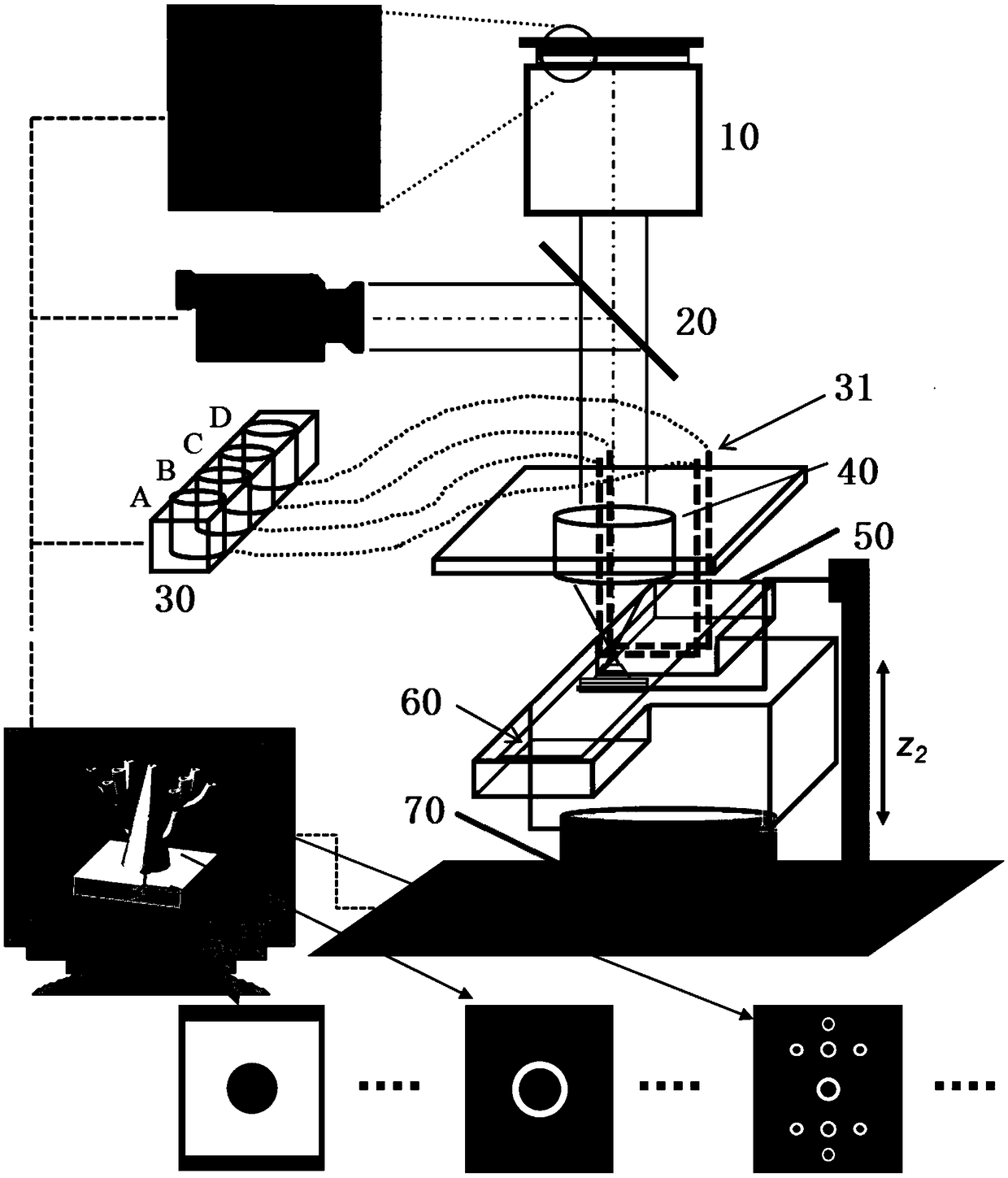
[0033] Such as figure 1 As shown, the multi-material micro-stereolithography system includes: an optical machine 10 , an electron (radiation) beam splitter 20 , a detergent 31 , a resin delivery 30 , a projection lens 40 , a scraper 50 , a film 60 and a container 70 .

Embodiment 2

[0035] A printing method using sacrificial materials in microstructure 3D photo-curing printing, comprising the following steps:

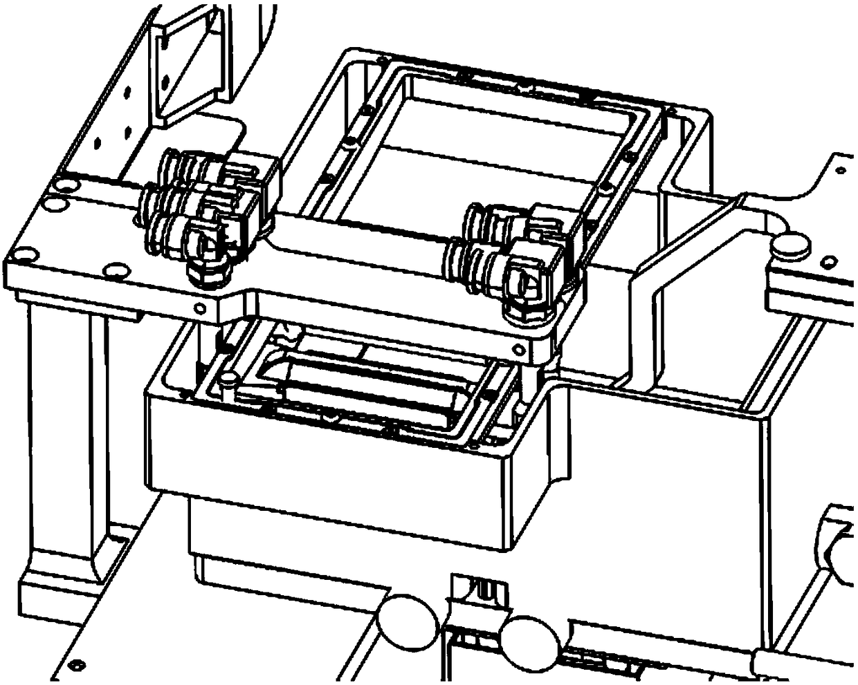
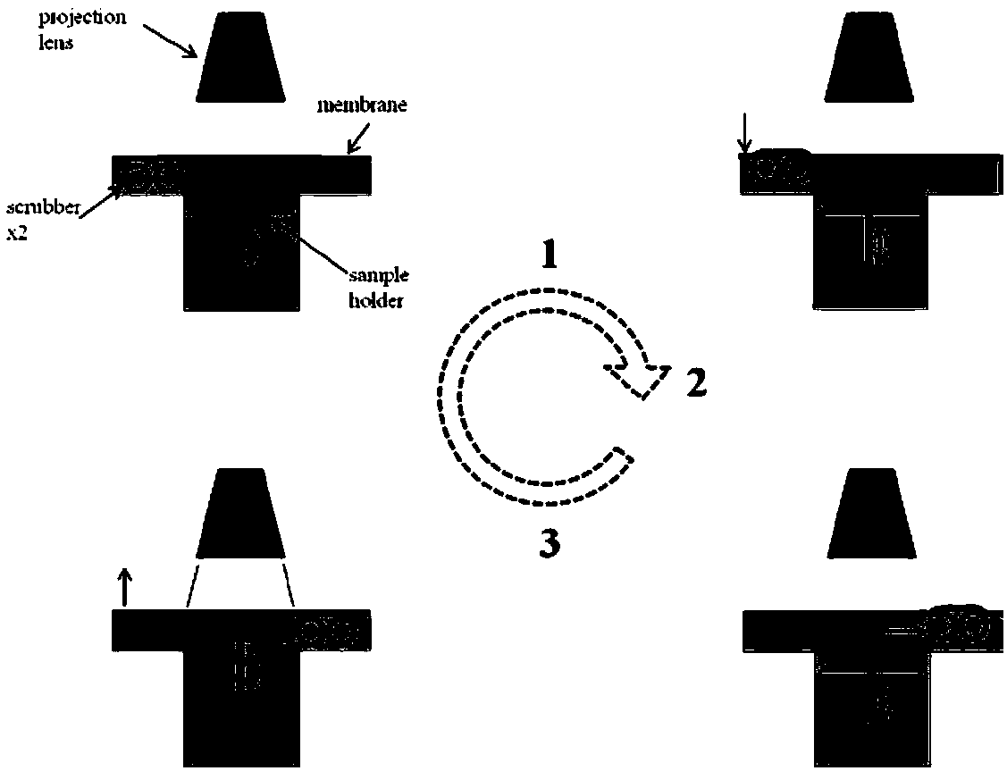
[0036] A projection lens projects the image on the DLP onto the lower surface of the film where the resin contacts, where the resin monomers react photochemically to cross-link into a solid. The material of the membrane here can be PDMS, PFA or other transparent films with a thickness ranging from 25 microns to 100 microns. The system has two parallel scrapers ( figure 2 ), to scrape off the resin, scrape the top film 0.5mm deep. Two resins are attached to each spatula. When working, the scraper that goes ahead scrapes off the old resin, and the scraper that goes behind applies resin backwards, as shown in Figure (3). In MCSL, there are two cases of resin switching (Figure 4). One is to switch resin between printing layers, one resin is printed on another resin, and after the scraper coats the new resin on the film, the sample is moved to the d...


PUM

PropertyMeasurementUnit
Thicknessaaaaaaaaaa

Abstract

The invention provides application of a sacrificial material to microstructure 3D light curing printing. The application includes the following steps: step A, an image on an digital light processor (DLP) is projected to the contact face of a film and resin through a projection lens in a multi-material micro-stereoscopic lithography system, and resin monomers are subjected to photochemical reactionand are cross-linked into a solid; step B, the system is provided with two parallel scrapers, the scraper travelling ahead scrapes the old resin away, and the scraper travelling behind smears the resin backwards; step C, the system replaces liquid and coats the film; and step D, different materials are subjected to the steps repeatedly, and printing of a 3D sample is completed layer by layer. Theapplication has the beneficial effects: how to print hung and movable parts in microscale is provided through the multi-material printing system, and thus microscale full 3D printing is achieved. Meanwhile, a formula of photosensitive resin used as a sacrificial mechanism in 3D printing is also provided, and the application of the sacrificial resin to a support structure is further optimized on the basis.

Description

technical field [0001] The invention relates to the field of 3D printing, in particular to the application of a sacrificial material in microstructure 3D photocuring printing. Background technique [0002] With the development of 3D printing technology, its application range is also expanding, from structural engineering, material engineering, to biological and medical engineering; from macroscopic scale (above centimeter level) to microscopic scale (below millimeter). However, the defects of traditional 3D printing technology are also beginning to appear, such as multi-material, high precision (less than 50 microns), suspension structure and active structure, etc. At the Hongguang scale, in order to print the suspension structure and the movable structure, the existing method is to print the support structure at the same time, and then manually remove the support structure later. These supporting structures are often small columnar groups. For microscopic scales, manual m...

Claims


Application Information

Patent Timeline
IPC IPC(8): B29C64/124B29C64/20B29C64/214B33Y10/00B33Y30/00
CPCB29C64/124B29C64/20B29C64/214B33Y10/00B33Y30/00
Inventor 夏春光黄立赵卓贺晓宁方绚莱
Owner 重庆摩方科技有限公司
Learn More