Packaging structure and current testing method of crimping device

A packaging structure and a technology for crimping devices, applied in the field of crimping devices, can solve the problems of increasing the volume of the crimping device and decreasing the power density, etc.

Active Publication Date: 2021-04-23
GLOBAL ENERGY INTERCONNECTION RES INST CO LTD
View PDF2 Cites 0 Cited by
  • Summary
  • Abstract
  • Description
  • Claims
  • Application Information

AI Technical Summary

Problems solved by technology
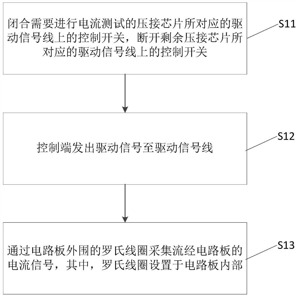
[0005] In view of this, an embodiment of the present invention provides a packaging structure and a current testing method of a crimping device to solve the problems in the prior art that the installation of the Rogowski coil causes the volume of the crimping device to increase and the power density to decrease

Method used


Image

  • Packaging structure and current testing method of crimping device
  • Packaging structure and current testing method of crimping device

Examples


Embodiment Construction

[0026] In order to make the purpose, technical solutions and advantages of the embodiments of the present invention clearer, the technical solutions in the embodiments of the present invention will be clearly and completely described below in conjunction with the drawings in the embodiments of the present invention. Obviously, the described embodiments It is a part of embodiments of the present invention, but not all embodiments. Based on the embodiments of the present invention, all other embodiments obtained by those skilled in the art without creative efforts fall within the protection scope of the present invention.

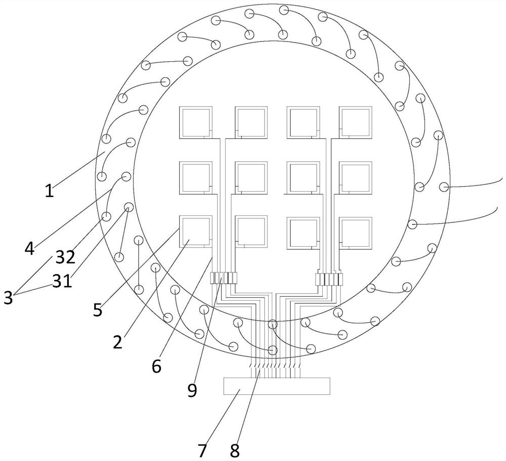
[0027] According to the first aspect, an embodiment of the present invention provides a package structure of a crimping device, such as figure 1 As shown, it includes several crimping chips 2 arranged on the circuit board 1, and the periphery of the circuit board 1 is provided with a number of dislocation via holes 3, and conductive wires 4 are sequentially w...


PUM


Abstract

The invention relates to the technical field of crimping devices, and specifically discloses a packaging structure and a current testing method of a crimping device. The packaging structure includes a plurality of crimping chips arranged on a circuit board. holes, conductive wires are sequentially wound around each of the dislocation via holes along the dislocation direction to form a Rogowski coil. On the one hand, the Rogowski coil can be used to detect the current of the crimping chip on the circuit board; on the other hand, the Rogowski coil is equivalent to being directly installed inside the circuit board, which reduces the space occupied by the Rogowski coil and does not need to expand the entire crimping device The size of the packaging structure can still ensure the high power density of the crimping device as a whole. In addition, since the Rogowski coil is directly arranged inside the circuit board, there is no need to assemble the Rogowski coil, which is very convenient to use.

Description

technical field [0001] The invention relates to the technical field of crimping devices, in particular to a packaging structure and a current testing method of a crimping device. Background technique [0002] At present, high-power IGBT devices for power systems mainly include soldering IGBT devices and crimping IGBT devices. Among them, crimping IGBT devices are widely used because of their unique short-circuit failure mode characteristics, easy series connection, and compact structure. [0003] However, it is precisely because of the compact internal space of the crimp-type IGBT device that it is difficult to install a current sensor inside it to monitor its operating status. Especially when crimping devices are installed on inverters, power units and other equipment, only the total current can be monitored, and the current of each chip inside cannot be monitored individually to evaluate their working status and service life. [0004] In order to solve the above problems,...

Claims


Application Information

Patent Timeline
Patent Type & Authority Patents(China)
IPC IPC(8): H01L23/64G01R19/00
CPCG01R19/0092H01L23/645H01L2223/64
Inventor 李金元吴鹏飞李尧圣王鹏崔梅婷
Owner GLOBAL ENERGY INTERCONNECTION RES INST CO LTD
Why Eureka
Try Eureka