Device and method for composite gas injection carbon reduction molten copper slag

A technology of composite gas and gas generating device, applied in the field of metallurgical process and equipment, can solve the problems of insufficient reduction, increased processing difficulty, low reduction efficiency, etc. Effect

Active Publication Date: 2020-07-24
HANGZHOU DIANZI UNIV
View PDF4 Cites 0 Cited by
  • Summary
  • Abstract
  • Description
  • Claims
  • Application Information

AI Technical Summary

Problems solved by technology

However, conventional carbonaceous solid reducing agents are easy to float on the surface of slag, resulting in insufficient reduction and low reduction efficiency; gaseous reducing agents such as natural gas are prone to excessive reduction, resulting in increased difficulty in subsequent processing and greater safety hazards

Method used


Image

  • Device and method for composite gas injection carbon reduction molten copper slag
  • Device and method for composite gas injection carbon reduction molten copper slag
  • Device and method for composite gas injection carbon reduction molten copper slag

Examples


Embodiment 1

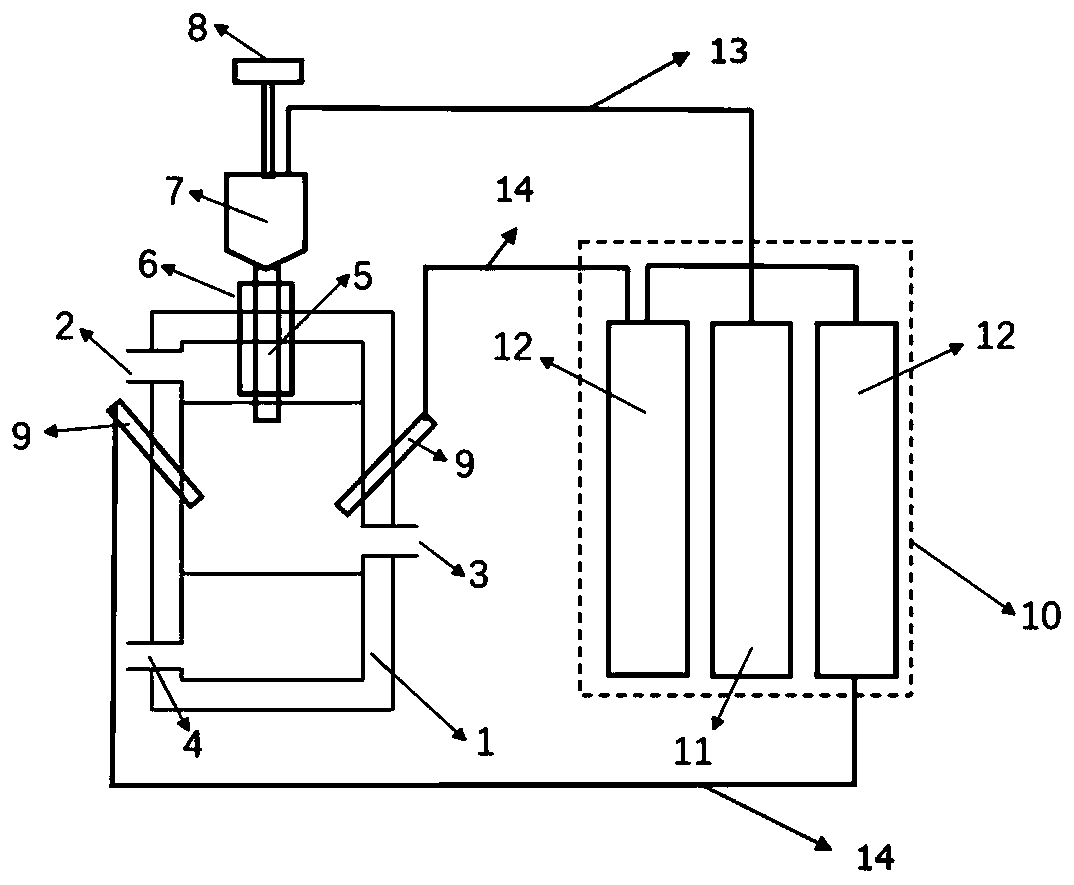
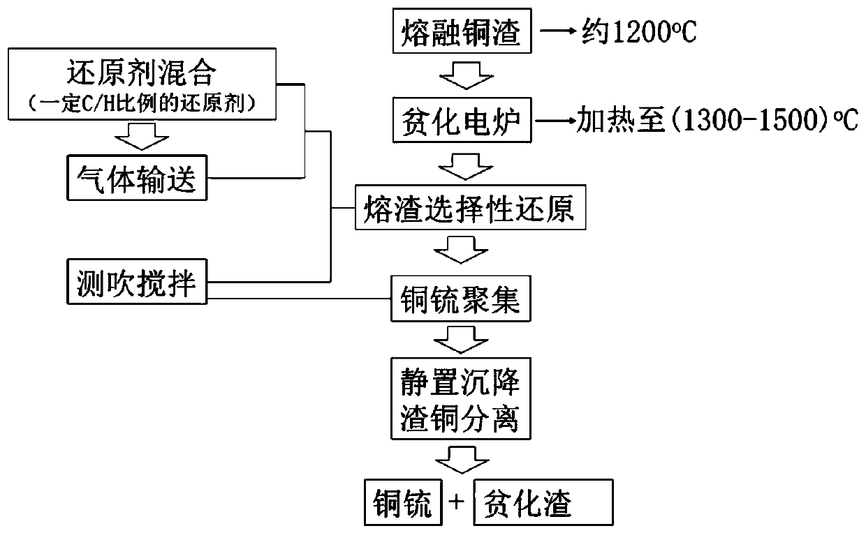
[0053] This embodiment is to selectively reduce the magnetite phase in the slag. The experimental process is a laboratory-scale experiment. During the depletion process, the electric resistance furnace is used to heat the depleted electric furnace. The reaction vessel is designed according to the patent requirements, and the slag processing capacity is about 5kg. This embodiment adopts figure 1 The device shown and figure 2 The process flow shown handles molten copper slag as follows:

[0054] Firstly, put the smelting slag into the electric resistance furnace and raise the temperature to 1400°C to make the slag have good fluidity; secondly, design the molar ratio of the top-blowing reducing agent to be 1:2 (actual reducing agent is CH 4 , flow rate 40L / min, pressure 0.2MPa), the inert gas for transportation is Ar gas, the flow rate is 40L / min, the pressure is 0.2MPa, the injection time is 30min, and the inert gas for side blowing and stirring is Ar gas, the flow rate is 40...

Embodiment 2

[0057] This example is for reduction preparation of copper-iron alloy. The experimental process is a scale-up test. In the depletion process, the electric furnace for heating the depletion is an induction furnace. The reaction vessel is designed according to the patent requirements, and the slag processing capacity is about 500kg. This embodiment adopts figure 1 The device shown and figure 2 The process flow shown handles molten copper slag as follows:

[0058] Firstly, put the smelting slag into the induction furnace and raise the temperature to 1500°C to make the slag have good fluidity; secondly, design the molar ratio of the top-blown reducing agent to be 1:4 (actual reducing agent is carbon powder and H 2 , H 2 The flow rate is 100Nm 3 / h, pressure 0.3MPa), the inert gas for transportation is Ar gas, and the flow rate is 100Nm 3 / h, the pressure is 0.3MPa, the injection time is 60min, and the inert gas used for side blowing and stirring is Ar gas, and the flow rate ...


PUM


Abstract

The invention relates to a device and method for copper slag pyrogenic process reduction and dilution and belongs to the technical field of metallurgy technologies and equipment. The device comprisesa dilution electric furnace and a gas generation device. The top of the dilution electric furnace is connected with a mixing bin through a top blowing spray gun. The gas generation device comprises areducing gas device and inert gas devices, gas outlets of the reducing gas device and the inert gas devices communicate with a gas inlet of the mixing bin through first pipelines. Reducing gas and carbon powder are mixed in the mixing bin to form a reducing agent with the needed ratio, under the effect of inert gas, the reducing agent is sent into the dilution electric furnace through the top blowing spray gun, side blowing spray guns are arranged on the side wall of the dilution electric furnace, gas outlets of the inert gas devices are further connected with the side blowing spray guns through second pipelines. The inert gas is used for conveying the reducing agent into the molten copper smelting slag, conveying of the carbon reducing agent can be achieved, advantages and disadvantages of various reducing agents are effectively balanced, the technological process is simple, and adaptability is high.

Description

technical field [0001] The invention relates to a device and method for reducing and depleting copper slag by fire method, belonging to the technical field of metallurgical technology and equipment. Background technique [0002] In the process of copper pyrometallurgy, the strong oxidation blowing process is usually used, which is beneficial to improve the grade of copper matte products, but on the other hand, it also correspondingly increases the loss of copper and other useful metals in the slag. Slag is the most important by-product in the copper smelting process, which contains a considerable amount of important non-ferrous resources such as Cu, Co, and Ni. Slag depletion has become one of the necessary processes in the copper smelting process. With the continuous consumption of energy and resources, it is of great strategic significance to develop a new copper slag depletion process with energy saving, environmental protection and high recovery rate to promote the susta...

Claims


Application Information

Patent Timeline
Patent Type & Authority Patents(China)
IPC IPC(8): C22B7/04C22B15/00
CPCC22B7/001C22B7/04C22B15/0052Y02P10/20
Inventor 张怀伟
Owner HANGZHOU DIANZI UNIV
Why Eureka
Try Eureka