Eureka AIR delivers breakthrough ideas for toughest innovation challenges, trusted by R&D personnel around the world.

Liquid-state CO2 washing method of petroleum industry oil dirt equipment and facilities

A technology for oil industry and oil pollution, which is applied in the field of liquid CO2 cleaning of oil pollution equipment and facilities in the oil industry. The effect of recycling and simple conveying device

Pending Publication Date: 2019-03-15
董恬纲
View PDF6 Cites 2 Cited by
  • Summary
  • Abstract
  • Description
  • Claims
  • Application Information

AI Technical Summary

Problems solved by technology

These methods all exist: 1. The cleaning process is cumbersome, time-consuming and labor-intensive, and the cleaning is not easy to complete, which is easy to cause damage and corrosion, and destroys the smoothness of the surface of the integrity of the parts.
2. The cleaning process will produce a large amount of viscous oil film, foam, and fiber garbage, which will bring more troubles for further follow-up disposal
3. Discarded solids and leaked sewage will directly pollute the land environment
4. The collection, concentration, harmless treatment and recycling of dirt and sewage require more special equipment and technologies
Bring more extra work to the oil extraction work, which seriously affects the production cost of crude oil

Method used


Image

  • Liquid-state CO2 washing method of petroleum industry oil dirt equipment and facilities
  • Liquid-state CO2 washing method of petroleum industry oil dirt equipment and facilities
  • Liquid-state CO2 washing method of petroleum industry oil dirt equipment and facilities

Examples


Embodiment Construction

[0028] The present invention will be described in further detail below in conjunction with the example of workover operation shown in the accompanying drawings:

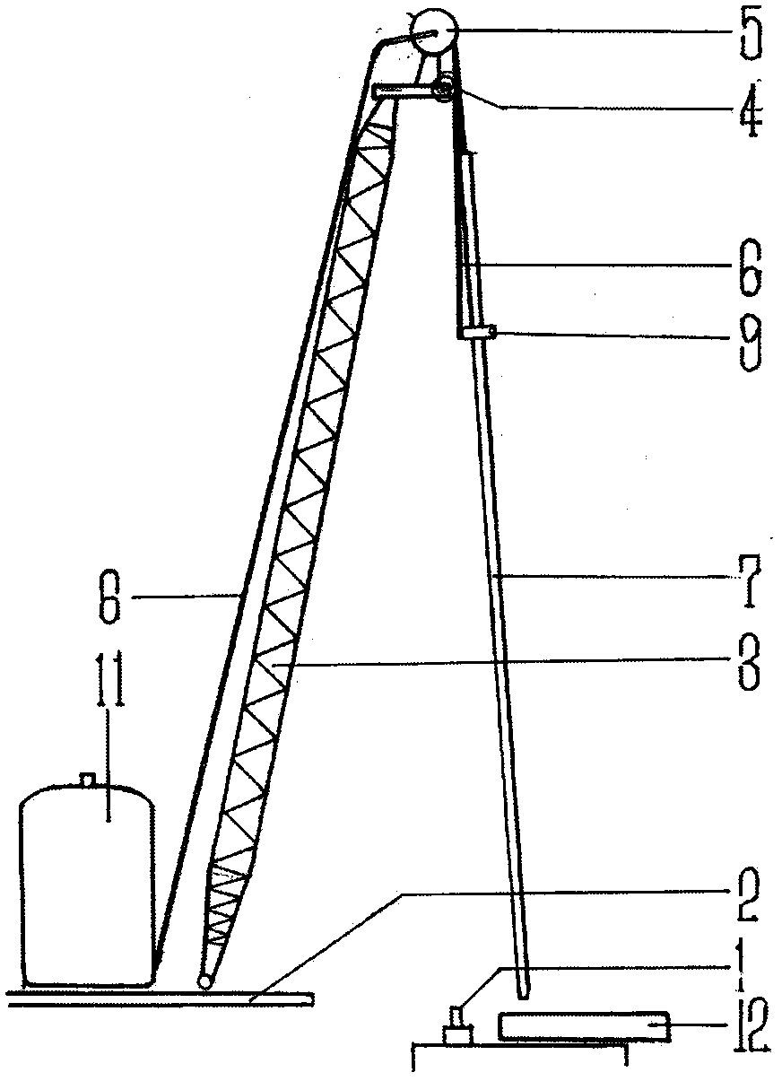
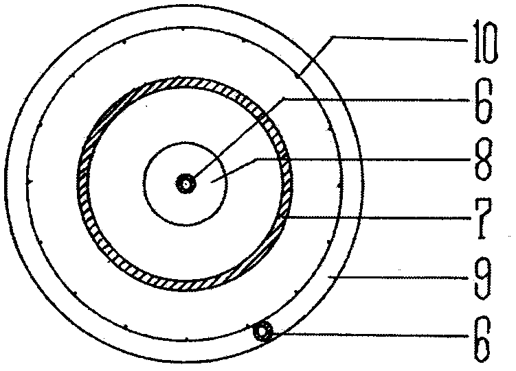
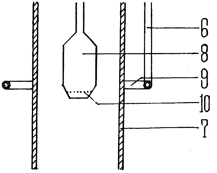
[0029] Such as figure 1 As shown: the workover operation needs to pass the pulley 4 at the top of the tower 3 provided on the workover vehicle platform 2, and the sucker rod and the oil well pipe 7 are hoisted out section by section by the wellhead 1. For sucker rods immersed in oil wells with a large amount of oil stains on the outside and oil well pipes 7 with a lot of oil stains on the inner and outer walls, after being lifted from the wellhead 1, they are pulled obliquely above the oil receiving groove 12, and the sucker rods pass through the annular centripetal jet Nozzle 9 emits liquid CO from capstan 5 2 The delivery pipeline 6 is from top to bottom, and the liquid CO injected by the downward-sloping jet hole 10 2 Rapid and thorough peeling from top to bottom to remove sticky and oil stains. The oil well pi...


PUM


Abstract

The invention discloses a liquid-state CO2 washing method of petroleum industry oil dirt equipment and facilities. Liquid-state CO2, a storing device, a conveying pipeline, a spraying device and an oil receiving groove bag are involved in the method. The method is characterized in that the characteristics of ultralow viscosity, ultra-strong mobility, ultra-strong permeability and ultra-strong adsorption property of the liquid state CO2 are utilized, and the flexible conveying pipeline and the spraying device strip and eliminate oil dirt rapidly and thoroughly at a time and collects and recycles the oil dirt for fixed or movable oil dirt oil field equipment or devices in the manner of extending in the single direction from top to bottom and from inside to outside. Compared with the prior art, oil dirt waste is not generated in the washing process, sewage containing oil and chemical agent and needing secondary treatment is not generated, new toxic and harmful substance is not generated,contaminant does not fall to the ground, the cleaning effect is thorough, fallen oil can be recycled, operation is simple, the cost is low, and the method is safe and environmentally friendly and hasgood application and popularization value.

Description

1. Technical field: [0001] The invention relates to the removal of oil stains in the process of using, maintaining, maintaining, repairing, rotating, replacing, and dismantling of oil polluted equipment and facilities in the petroleum industry, so as to prevent oil polluted from falling on the ground and pollute the environment, and to recycle, specifically, a Liquid CO for oil pollution equipment and facilities in the petroleum industry 2 the cleaning method. 2. Background technology: [0002] In the process of crude oil production in oil fields, a large number of equipment and facilities are in direct or indirect contact with crude oil, and a large amount of oil stains are attached. Oil must be removed. In the prior art, methods such as packaging and isolation of plastics and other film products, wiping of fiber foam products, and cleaning with chemical cleaning agents are used for disposal. These methods all exist: 1. The removal process is cumbersome, time-consuming a...

Claims


Application Information

Patent Timeline
IPC IPC(8): B08B7/00B08B3/02
CPCB08B3/02B08B7/0021
Inventor 张凌恺宋为国董兰田董恬纲
Owner 董恬纲
Why Eureka
Eureka Blog
Learn More