
Multi-point direct injecting and opposite shearing and fast-mixing radial injection low-nitrogen combustor

A low-nitrogen burner and burner technology, applied in the direction of burners, gas fuel burners, combustion methods, etc., can solve the problems of large construction costs and operating costs, detonation combustion process, boiler explosion, etc., to achieve low cost, Rapid blending, reducing the effect of heat release concentration

Active Publication Date: 2019-03-08
BEIHANG UNIV
View PDF7 Cites 4 Cited by
  • Summary
  • Abstract
  • Description
  • Claims
  • Application Information

AI Technical Summary

Problems solved by technology

At present, the surface premixed combustion scheme is relatively mature, but there is a risk of boiler explosion caused by the blockage of the metal mesh; the problems of premixed stable flame combustion are mainly the detonation during the ignition process and the shock during the combustion process, which are all faced by premixed combustion. problems and challenges
[0007] To sum up, to reduce the nitrogen oxide emissions of industrial furnaces or gas-fired boilers, many transformation technologies will increase the construction and operation costs, and pre-mixed combustion will bring unpredictable potential dangers.

Method used


Image

  • Multi-point direct injecting and opposite shearing and fast-mixing radial injection low-nitrogen combustor
  • Multi-point direct injecting and opposite shearing and fast-mixing radial injection low-nitrogen combustor
  • Multi-point direct injecting and opposite shearing and fast-mixing radial injection low-nitrogen combustor

Examples


Embodiment Construction

[0025] The present invention will be further described below in conjunction with the accompanying drawings and specific embodiments.

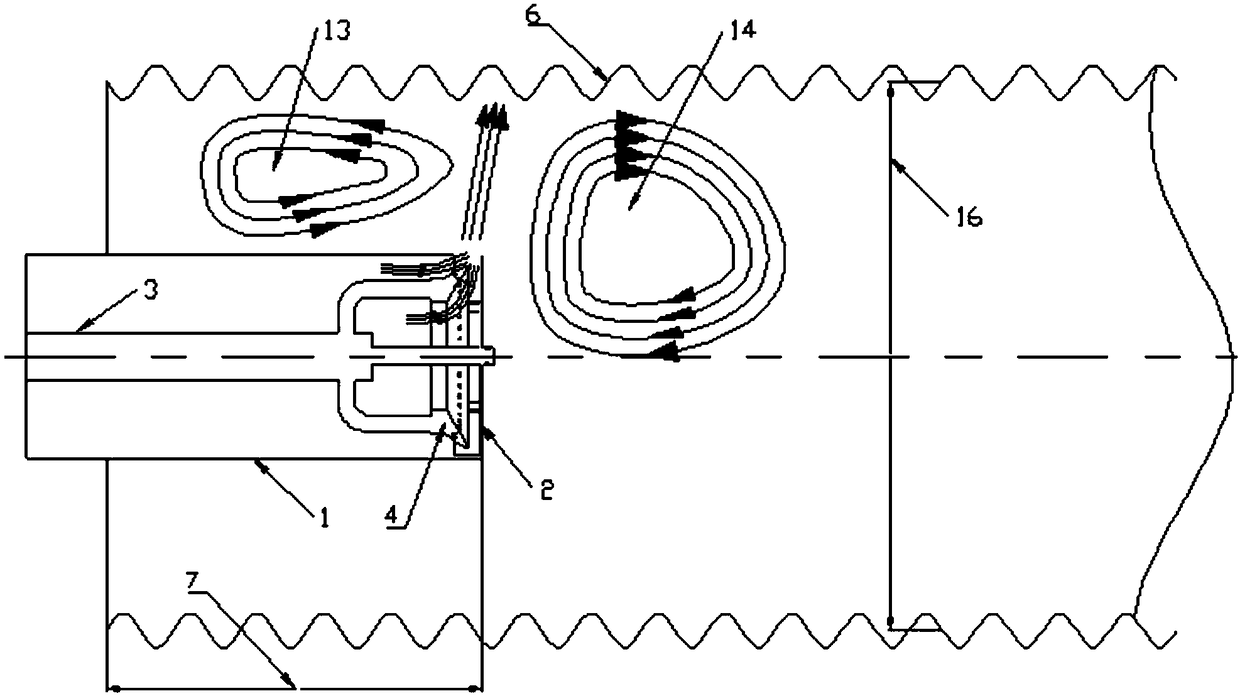
[0026] Such as figure 1 As shown, the embodiment of the present invention is mainly composed of a burner gas channel main pipe 1, a burner head baffle plate 2, a central fuel supply pipe 3, and a main road fuel injection device 4; the burner should be extended into the furnace of an industrial furnace or a gas-fired boiler 6 inside, to ensure a certain burner into the length 7;

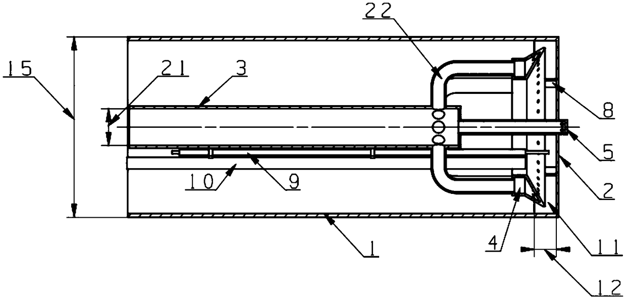
[0027] Such as figure 2 As shown, the ignition electrode 9 is fixed on the fuel pipe 10 of the ignition path, and is inserted into the vicinity of the central fuel supply pipe 3 in the burner as a whole to ensure that the ignition electrode 9 can work; A slot 11 with a radial opening is formed between the two, and the slot width 12 and the diameter 15 of the outer ring of the main body of the burner gas passage have a certain ratio range to ensure that the gas flow ...


PUM


Abstract

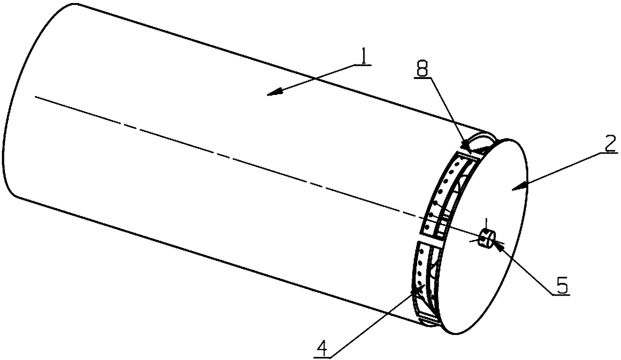
The invention discloses a multi-point direct injecting and opposite shearing and fast-mixing radial injection low-nitrogen combustor. The combustor is composed of a combustor gas circuit main pipe, acombustor head baffle, a central fuel supply pipe, a main path fuel injection device and an ignition path system; a seam groove with a radial opening is formed between the tail end of the combustor gas path main pipe and the combustor head baffle, gas is accelerated out through the radial seam groove after passing by the two sides of the main path fuel injection device, gaseous fuel is transversely sprayed into the accelerated gas flow through small holes in the two sides of the fuel injection device, the gas flow at the two sides of the fuel injection device is subjected to intersection shearing, the mixing of the gas and the fuel is accelerated, and the mixed gas is injected into a hearth through the radial groove; one stream of the mixed gas flow is deflected to the downstream after being collided with the hearth, so that a mainstream vortex is formed, the other stream of the mixed gas flow is deflected to the upstream, and an upstream vortex is formed; and the fuel is direct injected in a multi-point mode, the equivalent ratio is uniformly distributed, the flame impacts the wall surface of the hearth, heat exchange is accelerated, the internal circulation of the flue gas is formed due to the presence of the upstream vortex, and the comprehensive characteristics achieve the effect of reducing the emission of nitrogen oxide of the combustor.

Description

technical field [0001] The present invention relates to the technical field of burners, in particular to a multi-point direct injection opposite-cut fast-mixing radial injection low-nitrogen burner, which is a burner using gaseous fuel and is suitable for industrial furnaces or gas boilers using gaseous fuel. It can make the distribution of combustion equivalence ratio more uniform, the internal circulation of flue gas, and reduce the emission of nitrogen oxides. Background technique [0002] At present, Beijing, the capital, is seriously affected by smog every year. In the early stage, a comprehensive transformation of Beijing's coal-fired boilers was carried out to replace coal with gas, reducing pollutant emissions from energy sources, and achieving the role of controlling air pollution. The low-nitrogen transformation of gas-fired boilers is to reduce nitrogen oxides and water vapor in the air, and it is also a key project task in the Beijing Clean Air Action Plan. At p...

Claims


Application Information

Patent Timeline
Patent Type & Authority Applications(China)
IPC IPC(8): F23D14/02F23D14/46
CPCF23D14/02F23D14/46
Inventor 林宇震王晓峰王建臣张弛
Owner BEIHANG UNIV
Learn More