
Semiconductor device for power supply control and power supply device, and discharging method for X capacitor

A power control and semiconductor technology, applied in the field of semiconductor devices for power control, can solve the problems of insufficient low power consumption, failure to detect plug discharge, etc., and achieve the effect of reducing power consumption

Inactive Publication Date: 2019-03-05
MITSUMI ELECTRIC CO LTD
View PDF13 Cites 3 Cited by
  • Summary
  • Abstract
  • Description
  • Claims
  • Application Information

AI Technical Summary

Problems solved by technology

However, in the invention described in Patent Document 3, in the standby mode, the internal power supply circuit, the circuit for starting the IC, the circuit for controlling the start-up, the discharge circuit of the X capacitor, the reference voltage circuit, and the bias circuit are operated. , so there is a problem of insufficient low power consumption during standby
However, in order to reduce power consumption, if the operation of the discharge circuit of the X capacitor is stopped in the standby mode, there is a problem that the discharge of the X capacitor cannot be detected when the plug is pulled out in the standby mode.

Method used


Image

  • Semiconductor device for power supply control and power supply device, and discharging method for X capacitor
  • Semiconductor device for power supply control and power supply device, and discharging method for X capacitor
  • Semiconductor device for power supply control and power supply device, and discharging method for X capacitor

Examples


Embodiment Construction

[0061] Hereinafter, preferred embodiments of the present invention will be described with reference to the drawings.

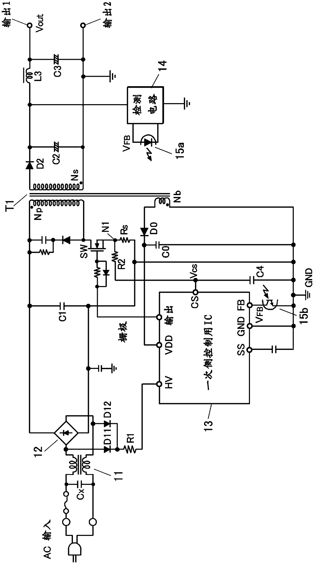
[0062] figure 1 It is a circuit configuration diagram showing one embodiment of an AC-DC converter to which the isolated DC power supply device of the present invention is applied.

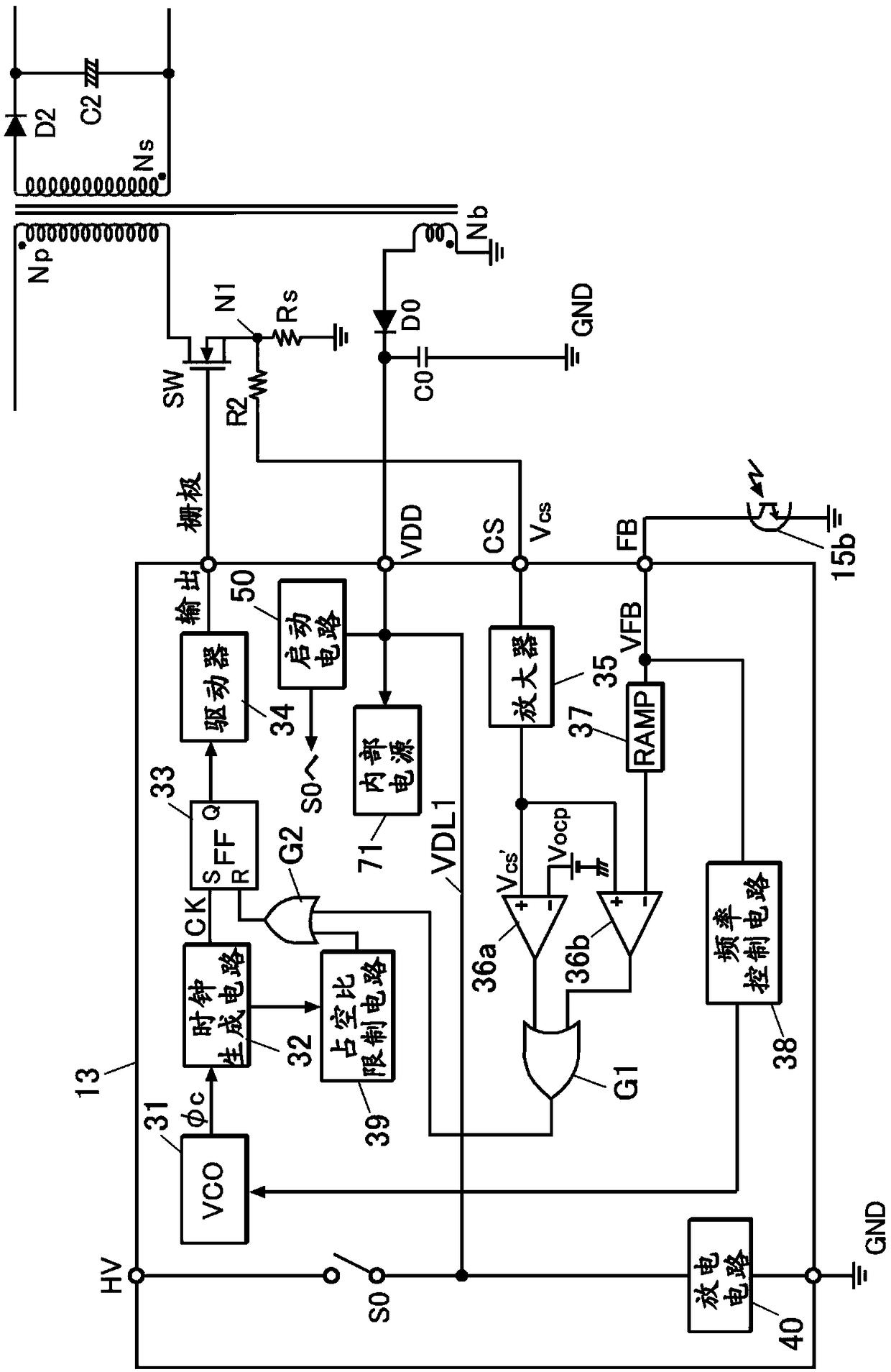
[0063] The AC-DC converter of this embodiment has an X capacitor Cx connected between AC terminals to attenuate normal mode noise, a noise cutting filter 11 composed of a common mode coil, etc., rectifies an alternating voltage (AC) and A diode bridge circuit 12 for converting a DC voltage, a filter capacitor C1 for filtering the rectified voltage, a voltage conversion transformer T1 having a primary side winding Np, a secondary side winding Ns, and an auxiliary winding Nb, and the transformer T1 The primary side winding Np is connected in series with a switching transistor SW composed of an N-channel MOSFET, and a power control circuit 13 for driving the switching transistor SW....


PUM


Abstract

The invention provides a semiconductor device for power supply control and a power supply device, and a discharging method for an X capacitor. The invention aims to reduce the circuit scale of the circuit which performs discharging of the X capacitor and to reduce the power consumption and the chip size in the semiconductor device for control forming an insulated direct-current power supply device. The semiconductor device for power supply control includes: a high-voltage input start terminal (HV) to which alternating-current voltage of AC input or voltage rectified in a diode bridge is input;a plurality of voltage comparison circuits (CMP1, CMP2) which connect input terminals to the high-voltage input start terminal; a timer circuit (TMR) which starts to measure a predetermined time at atiming of rising and / or falling of output of the plurality of voltage comparison circuits; and a discharging unit (Rd, Sd) between the high-voltage switching element (S0) and a ground point, whereinthe discharging unit is made conductive when the predetermined time is measured by the timer circuit.

Description

technical field [0001] The present invention relates to a semiconductor device for power supply control, and particularly relates to a technology effectively used for a semiconductor device for primary side control constituting an isolated DC power supply device including a transformer for voltage conversion. Background technique [0002] In the DC power supply device, there is an isolated AC power supply device composed of a diode bridge circuit that rectifies the AC power supply, and a DC-DC converter that steps down the DC voltage rectified by the current and converts it into a DC voltage of a desired potential. -DC converter. [0003] In an isolated AC-DC converter, an X capacitor is generally connected between the AC terminals in order to attenuate normal-mode noise, and in order to quickly discharge the charge remaining in the X capacitor when the plug is pulled out from the outlet, and X A resistor for discharging is connected in parallel to the capacitor. [0004] ...

Claims


Application Information

Patent Timeline
Patent Type & Authority Applications(China)
IPC IPC(8): H02M7/219H02M3/335
CPCH02M3/33523H02M7/219H02M1/32H02M3/33507Y02B70/10H02M1/0032H02M1/322H02M1/08
Inventor 松田裕树
Owner MITSUMI ELECTRIC CO LTD
Learn More