
3D printing method of metal part of hollowed structure

A suspended structure and 3D printing technology, applied in the field of 3D printing manufacturing, can solve the problems of low manufacturing efficiency, high manufacturing cost, and low molding quality, and achieve the effects of ensuring stability, controlling manufacturing costs, and improving molding quality

Active Publication Date: 2019-03-05
SHENZHEN SILVER BASIS TECH
View PDF8 Cites 6 Cited by
  • Summary
  • Abstract
  • Description
  • Claims
  • Application Information

AI Technical Summary

Problems solved by technology

[0004] The purpose of the present invention is to provide a 3D printing method for suspended structural metal parts, aiming to solve the technical problems of low manufacturing efficiency, low molding quality and high manufacturing cost in the manufacture of suspended structural parts in the 3D printing method in the prior art

Method used


Image

  • 3D printing method of metal part of hollowed structure

Examples


Embodiment Construction

[0022] Embodiments of the present invention are described in detail below, examples of which are shown in the drawings, wherein the same or similar reference numerals designate the same or similar elements or elements having the same or similar functions throughout. The embodiments described below by referring to the figures are exemplary and are intended to explain the present invention and should not be construed as limiting the present invention.

[0023] In describing the present invention, it should be understood that the terms "length", "width", "upper", "lower", "front", "rear", "left", "right", "vertical", The orientation or positional relationship indicated by "horizontal", "top", "bottom", "inner", "outer", etc. are based on the orientation or positional relationship shown in the drawings, and are only for the convenience of describing the present invention and simplifying the description, rather than Nothing indicating or implying that a referenced device or element...


PUM


Abstract

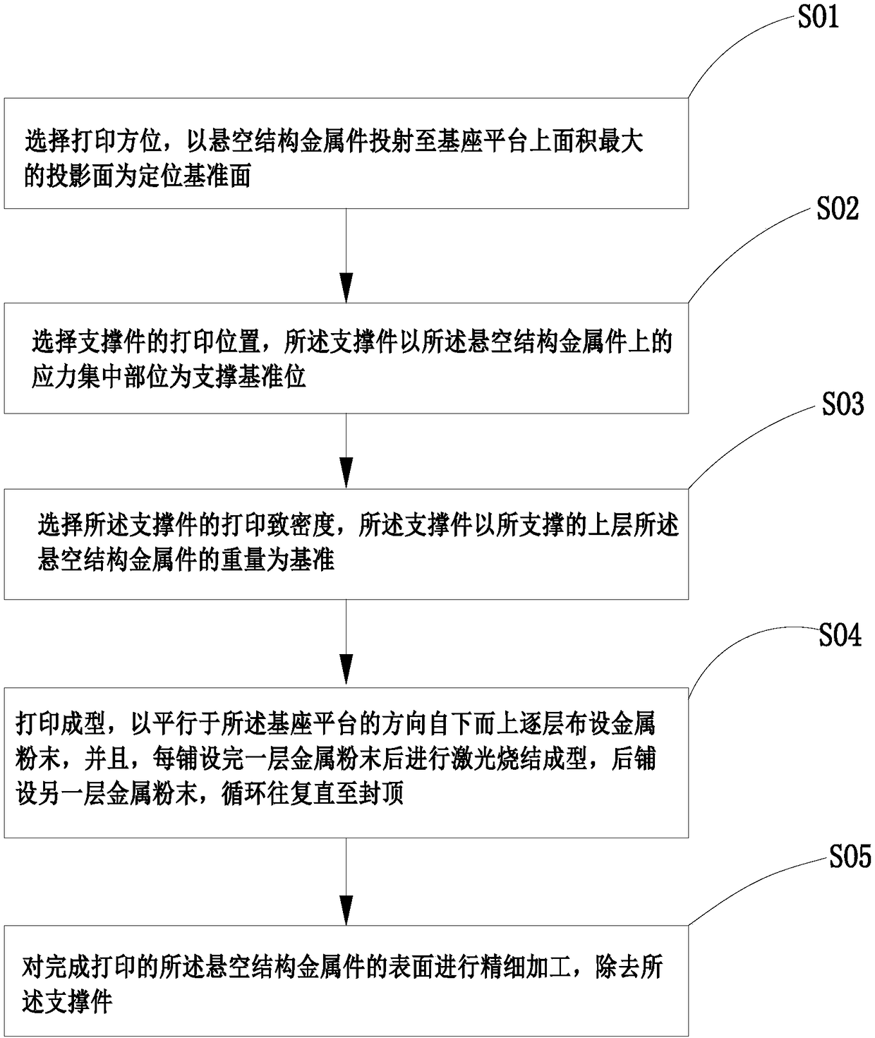
The invention relates to the technical field of 3D printing manufacturing, and provides a 3D printing method of a metal part of a hollowed structure. The 3D printing method comprises the following steps that firstly, a printing orientation is selected, and refers to the placement orientation of the metal part of the hollowed structure on a base platform; secondly, a printing position of a supporting part is selected, and the supporting part takes a stress concentrated part on the metal part of the hollowed structure as a supporting reference position; thirdly, the printing density of the supporting part is selected, and the supporting part take weight of the supported upper-layer the metal part of the hollowed structure as a benchmark; and finally, after early-stage preparation work is completed, printing forming is conducted in the following printing forming process, metal powder is laid layer by layer from bottom to top in the direction parallel to the base platform, laser sinteringforming is carried out after each layer of metal powder is laid, another layer of metal powder is laid after sintering is completed, the steps are carried out repeatedly until the last layer of metalpowder of the metal part of the hollowed structure is sintered, and then capping is carried out.

Description

technical field [0001] The invention relates to the technical field of 3D printing and manufacturing, and in particular provides a 3D printing method for metal parts with suspended structures. Background technique [0002] Additive manufacturing technology is a general term for a technology that is directly driven by a CAD model and accumulates materials into solid parts layer by layer or point by point. Compared with traditional cutting technology, it is a "top-down, layered manufacturing, step by step The idea of ​​additive manufacturing "layer by layer". The 3D printing technology of metal parts is to lay the metal powder layer by layer, and then use laser sintering to sinter the laid metal powder, so that one layer is laid and one layer is fired until it is fully formed. [0003] The so-called suspended structural parts refer to parts with holes, pores and external extensions on the main body of the structure. In the process of using traditional metal 3D printing to ma...

Claims


Application Information

Patent Timeline
IPC IPC(8): B22F3/105B22F5/10
CPCB22F5/10B33Y10/00B22F10/00B22F10/28Y02P10/25B22F10/20
Inventor 李芳伍世锋
Owner SHENZHEN SILVER BASIS TECH
Learn More