
Constant torque control method of permanent magnet synchronous motor based on position sensorless vector control

A permanent magnet synchronous motor, vector control technology, applied in the direction of single motor speed/torque control, control generator, vector control system, etc., can solve the problems of unstable state, inaccurate speed estimation, easy to enter unstable state and so on , to achieve the effect of stable operation and stable speed

Active Publication Date: 2020-07-24
ZHONGSHAN BROAD OCEAN
View PDF2 Cites 0 Cited by
  • Summary
  • Abstract
  • Description
  • Claims
  • Application Information

AI Technical Summary

Problems solved by technology

[0016] The purpose of the present invention is to provide a permanent magnet synchronous motor constant torque control method based on position sensorless vector control, to solve the problem in the prior art: it is very easy to enter an unstable state due to inaccurate speed estimation at low speed; when the torque command value deviates from When the load becomes heavier, the speed drops, and if the speed is not effectively controlled, it is easy to enter an unstable technical problem

Method used


Image

  • Constant torque control method of permanent magnet synchronous motor based on position sensorless vector control
  • Constant torque control method of permanent magnet synchronous motor based on position sensorless vector control
  • Constant torque control method of permanent magnet synchronous motor based on position sensorless vector control

Examples


Embodiment Construction

[0051] The present invention will be described in further detail below through specific embodiments and in conjunction with the accompanying drawings.

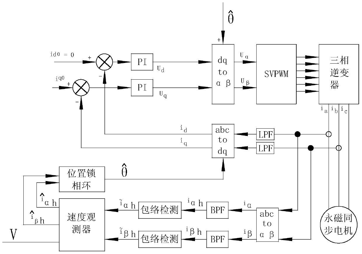
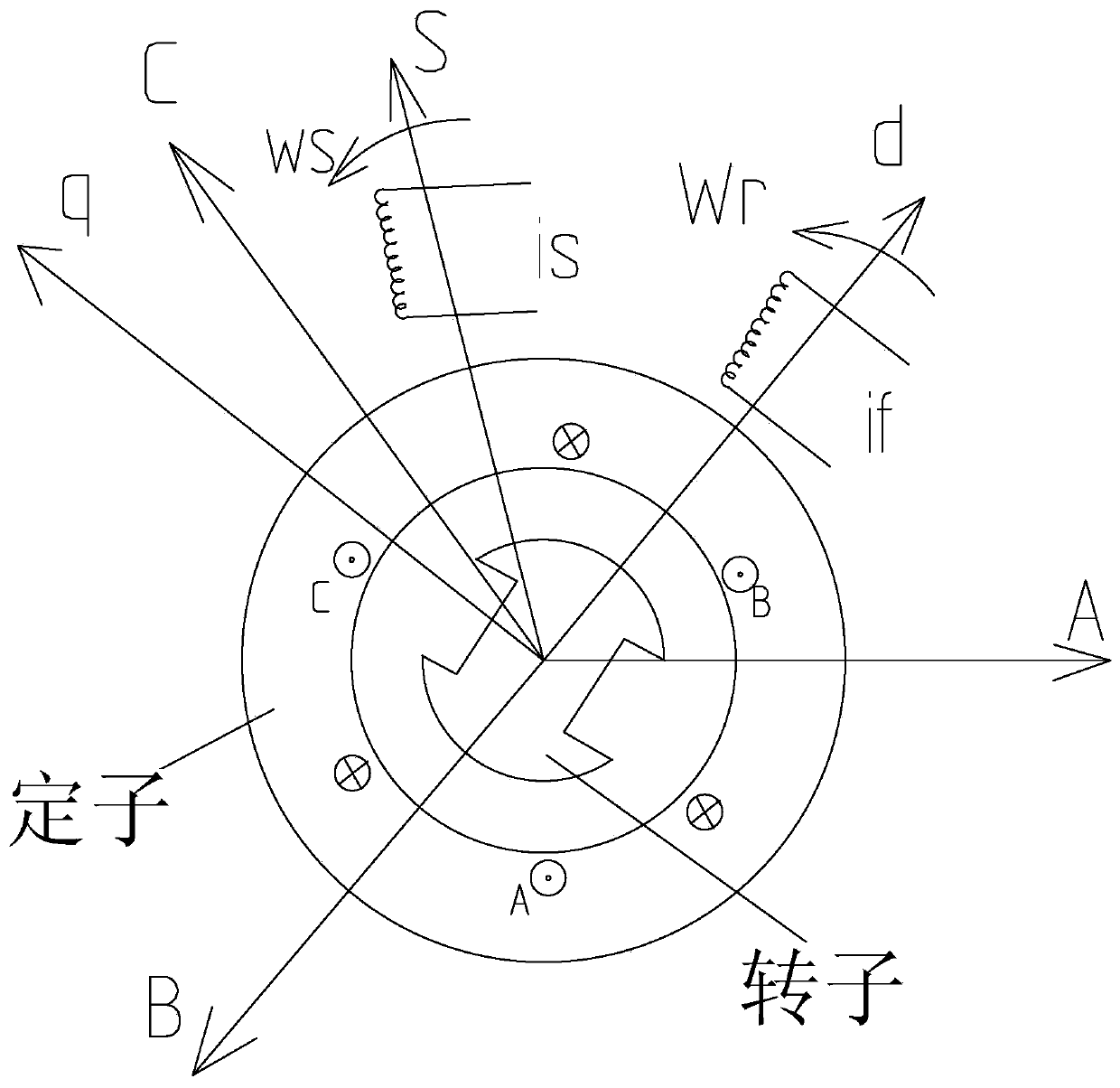
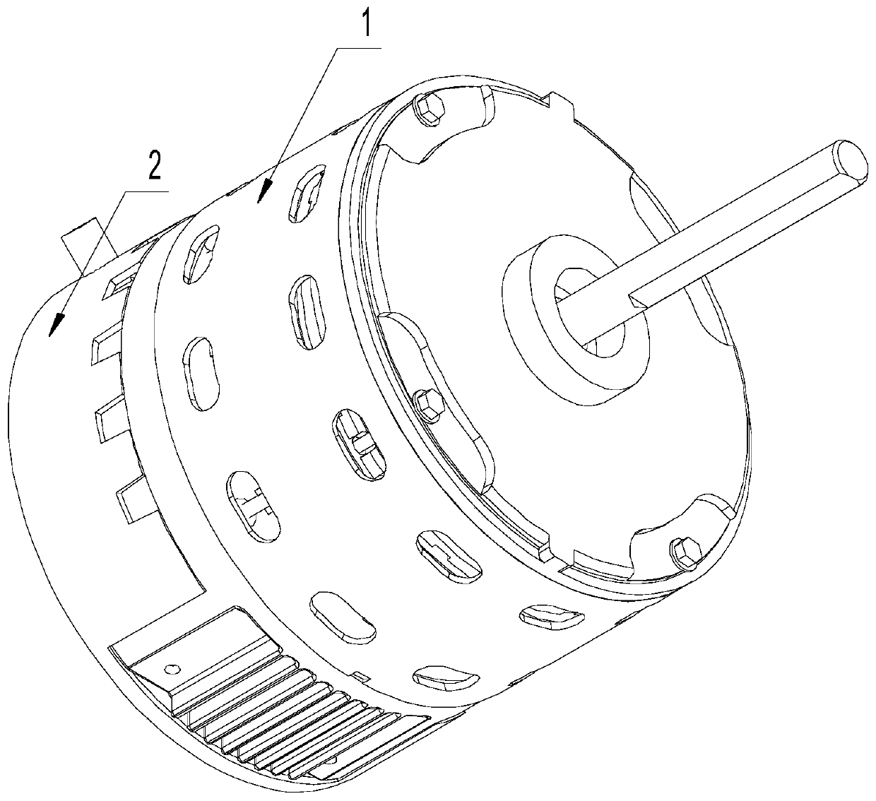
[0052] Such as image 3 , Figure 4 , Figure 5 As shown, for example: assume that the present invention is a three-phase permanent magnet synchronous motor, composed of a motor controller 2 and a motor unit 1, and the motor unit 1 includes a stator assembly 12, a rotor assembly 13 and a casing assembly 11, The stator assembly 13 is installed on the casing assembly 11, and the rotor assembly 13 is set on the inside or outside of the stator assembly 12. The motor controller 2 includes a control box 22 and a control circuit board 21 installed in the control box 22. The control circuit board 21 It generally includes a power supply circuit, a microprocessor, a bus voltage detection circuit, and an inverter. The power supply circuit supplies power to various parts of the circuit. The inverter controls the power on and off of the...


PUM


Abstract

A constant torque control method for a permanent magnet synchronous motor. The method includes: 1) starting a motor; setting a torque T of the motor; calculating a given current iq_limit on a q-axis based on the torque T; setting a target current iq_A on the q-axis to be equal to the given current iq_limit; and allowing the motor to operate in a constant torque control mode by a current-based proportional integral (PI) controller on the q-axis; 2) presetting a reference speed Vref1 of the motor; measuring a real-time speed V of the motor; when the real-time speed V is less than the reference speed Vref1, increasing an extra current delta_iq to the given current iq_limit to intervene the real-time speed V of the motor; and 3) measuring the real-time speed V of the motor; and calculating a speed difference Err=V−Vref2.

Description

Technical field: [0001] The invention relates to a constant torque control method of a permanent magnet synchronous motor based on a position sensorless vector control. Background technique: [0002] At present, there are generally three control methods for position sensorless vector control permanent magnet synchronous motors: constant torque control mode, constant speed control mode, or constant air volume control mode. [0003] For example, U.S. Patent No. 7,525,269 discloses a position sensorless 3-phase synchronous motor motor vector controller, which only discloses a current torque control mode for constant torque control. [0004] Chinese patent CN103929109 (A) also discloses a constant speed control method based on position sensorless vector control permanent magnet synchronous motor. [0005] Such as figure 1 As shown, the general block diagram of constant torque control is shown as figure 1 As shown, since the torque T is only related to the q-axis current, acco...

Claims


Application Information

Patent Timeline
Patent Type & Authority Patents(China)
IPC IPC(8): H02P21/24H02P21/00H02P25/022
CPCH02P21/0021H02P25/022H02P2207/05H02P21/24H02P25/024H02P6/18H02P21/13H02P21/18H02P6/08H02P21/06
Inventor 蓝竞豪边文清
Owner ZHONGSHAN BROAD OCEAN
Learn More