
Granulation system with thermal protection function

A thermal protection and functional technology, applied in the field of granulation system with thermal protection function, can solve the chemical corrosion of granulator, high temperature erosion of granulator, failure to control the thickness and shape of slag shell formation, etc. problems, to achieve the effect of simple and easy installation, help thermal protection, and increase the heat exchange area

Inactive Publication Date: 2019-02-22
CHONGQING UNIV
View PDF5 Cites 1 Cited by
  • Summary
  • Abstract
  • Description
  • Claims
  • Application Information

AI Technical Summary

Problems solved by technology

[0004] ①Based on CaO, MgO, SiO in slag 2 and other components, the granulator will have chemical corrosion problems
In addition, the working temperature of the granulator is usually around 1450°C, and long-term operation will lead to severe high-temperature corrosion of the granulator
This affects the service life and operational safety of the granulator
[0005] ②In the process of centrifugal granulation, slag shells will be formed on the upper surface of the granulator. At present, the thickness and shape of the slag shells have not been well controlled, and they have not been well utilized for use as Thermal protection of the granulator
[0006] ③ Due to the high-speed rotation of the granulator, it is difficult to measure the real-time temperature on the surface of the granulator, and the working temperature of the granulator cannot be reflected in real time, so that it is impossible to provide corresponding technical guidance for the thermal protection measures of the granulator

Method used


Image

  • Granulation system with thermal protection function
  • Granulation system with thermal protection function
  • Granulation system with thermal protection function

Examples


Embodiment Construction

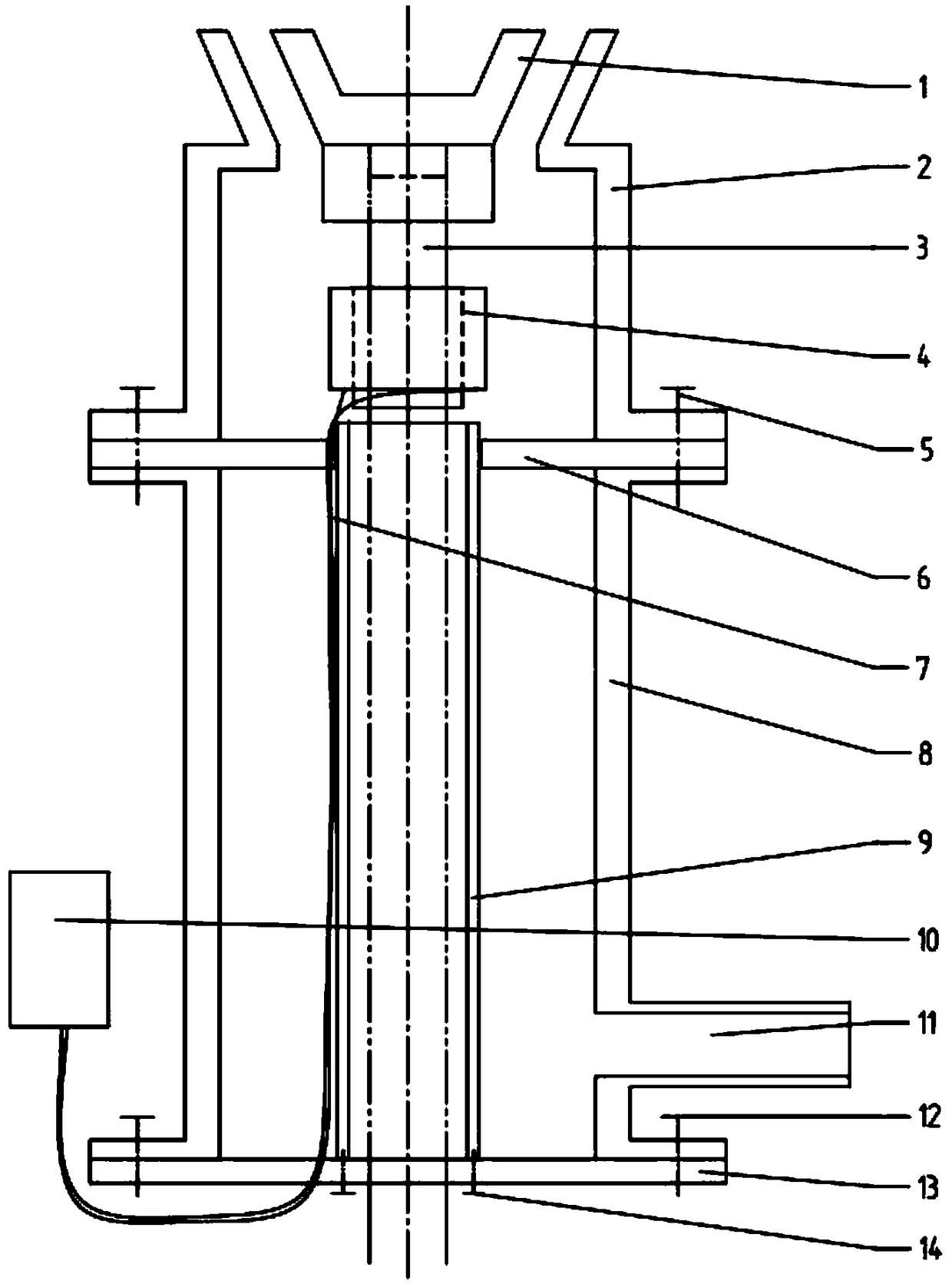
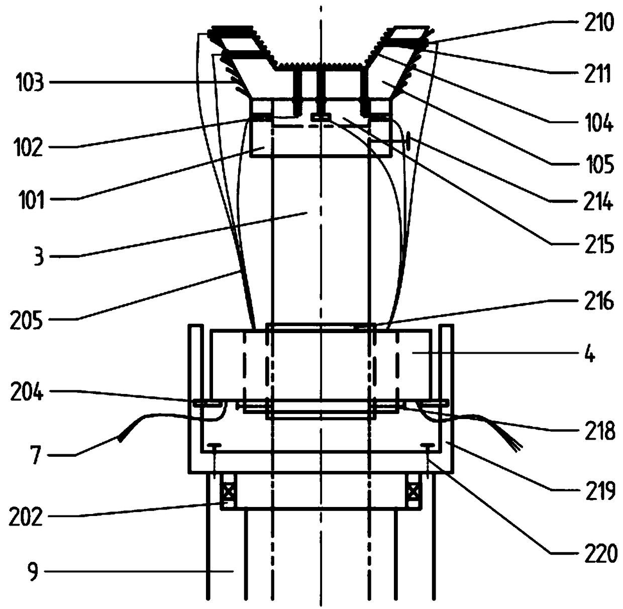
[0026] see Figure 1 to Figure 4 , a granulation system with heat protection function, comprising a rotating shaft 3, an auxiliary cooling air supply unit, a temperature monitoring unit and a granulator 1; the granulator 1 is fixed on the top of the rotating shaft 3; it is characterized in that:

[0027] The auxiliary cooling air supply unit provides cooling air for the temperature monitoring unit and the granulator 1; the auxiliary cooling air supply unit includes air cylinders 2, 8 and air inlet ducts 11; the air ducts are connected to the fan through the air inlet ducts 11; The temperature monitoring unit and the granulator 1 are arranged in the air duct;

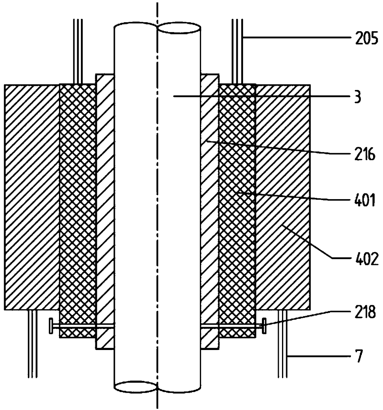
[0028] The temperature monitoring unit includes a plurality of thermocouples 210, through-aperture conductive slip rings 4, anti-rotation plates 204 and anti-rotation devices 219; a plurality of thermocouples 210 are arranged in the granulator 1, and the granulator 1 A number of thermocouple mounting holes are provided ...


PUM


Abstract

The invention discloses a granulation system with a thermal protection function. The granulation system with the thermal protection function comprises a rotating shaft, an auxiliary cooling air supplyunit, a temperature monitoring unit and a granulating device, wherein the granulating device is fixed at the top of the rotating shaft. The granulation system is characterized in that the auxiliary cooling air supply unit provides cooling air for the temperature monitoring unit and the granulating device; the auxiliary cooling air supply unit comprises an air duct and an air inlet pipeline; the air duct is connected with a fan through the air inlet pipeline; the temperature monitoring unit and the granulating device are arranged in the air duct; the temperature monitoring unit comprises a plurality of thermocouples, a through aperture conductive slip ring, a rotation stopping piece and a rotation stopping device; and the plurality of thermocouples are arranged in the granulating device, the rotation stopping device is arranged below the granulating device, the through aperture conductive slip ring is arranged on the rotating shaft in a sleeving mode and is fixed on the rotation stopping device through the rotation stopping piece. The granulation system can be widely applied to the fields of steel, metallurgy and the like.

Description

technical field [0001] The invention relates to the technical field of liquid slag granulation, in particular to a granulation system with thermal protection function. Background technique [0002] According to the data released by the "World Steel Yearbook 2017", it can be seen that in 2016, the world's pig iron production was 1.628 billion tons, of which China's pig iron production was 803 million tons, accounting for about 50% of the world's production. In the process of smelting iron and steel, slag high-temperature waste heat resources account for about 35% of high-temperature waste heat resources in iron and steel enterprises, of which blast furnace slag accounts for 28%. In general, the slag discharge temperature of blast furnace slag is between 1400-1550°C, and the sensible heat contained in each ton of blast furnace slag is 1260-1880MJ, which is equivalent to 60kg of standard coal. Under the current technology in our country, every ton of crude steel produced will ...

Claims


Application Information

Patent Timeline
Patent Type & Authority Applications(China)
IPC IPC(8): C21B3/08C21B3/06
CPCC21B3/06C21B3/08Y02W30/50
Inventor 朱恂代茂林王宏谢震廷廖强丁玉栋付乾夏奡张彪张亮
Owner CHONGQING UNIV
Learn More