Automatic cutting and polishing device

A technology of automatic cutting and movable blocks, which is applied in the direction of grinding machines, grinding workpiece brackets, grinding machine parts, etc., can solve the problems of low efficiency and large labor cost, and achieve smooth cutting, improved processing accuracy, accurate and stable positioning Effect

Pending Publication Date: 2019-02-19
LIAONING UNIVERSITY OF TECHNOLOGY
View PDF12 Cites 0 Cited by
  • Summary
  • Abstract
  • Description
  • Claims
  • Application Information

AI Technical Summary

Problems solved by technology

[0003] The purpose of the present invention is to provide an automatic cutting and grinding device, which makes the positioning of the workpiece more stable when cutting pipe fittings, and at the same time solves the problems of low efficiency, large labor costs and grinding stability caused by manual grinding, so as to solve the problems raised in the above background technology

Method used


Image

  • Automatic cutting and polishing device
  • Automatic cutting and polishing device
  • Automatic cutting and polishing device

Examples


Embodiment Construction

[0040] The following will clearly and completely describe the technical solutions in the embodiments of the present invention with reference to the accompanying drawings in the embodiments of the present invention. Obviously, the described embodiments are only some, not all, embodiments of the present invention. Based on the embodiments of the present invention, all other embodiments obtained by persons of ordinary skill in the art without making creative efforts belong to the protection scope of the present invention.

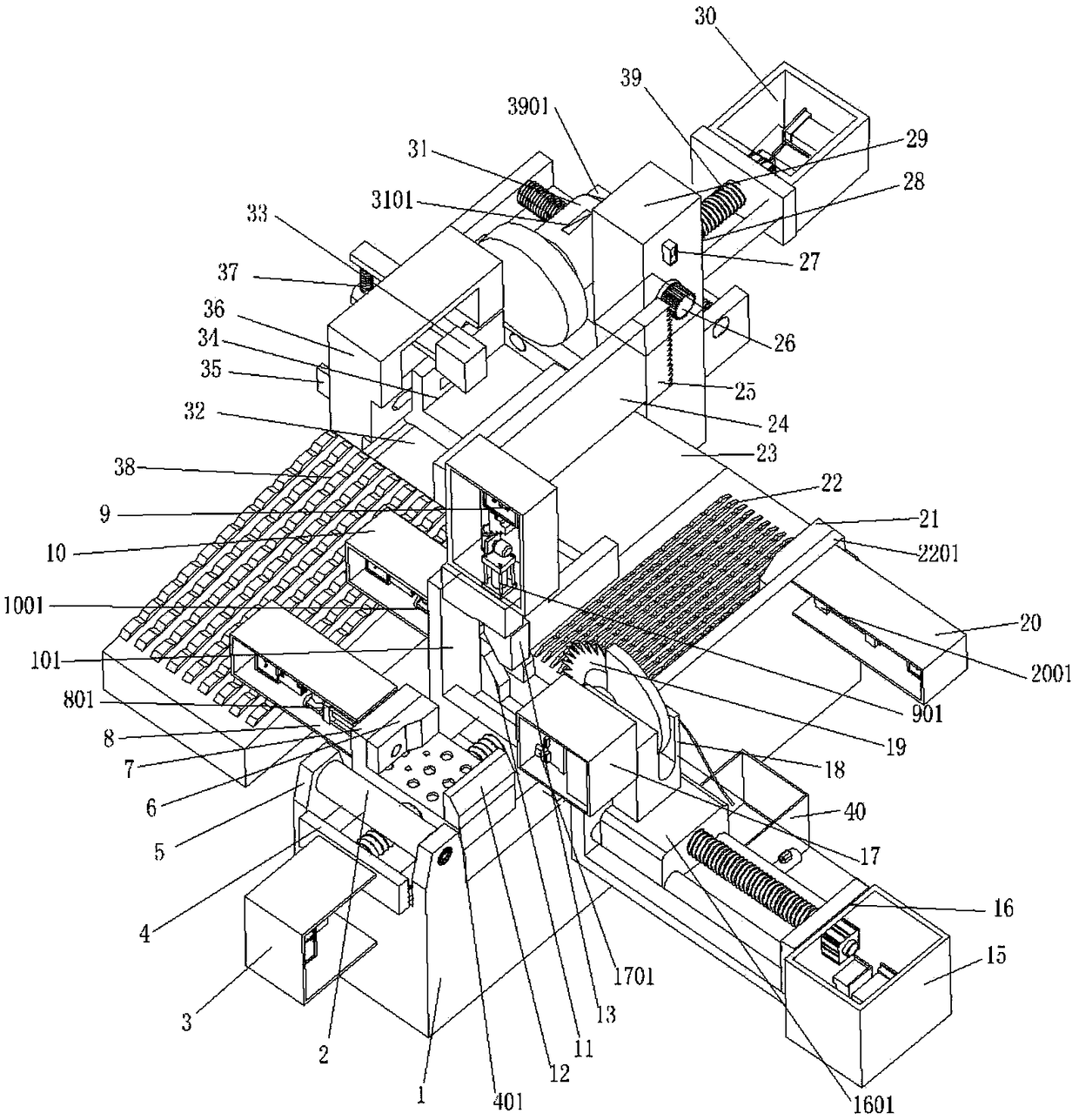
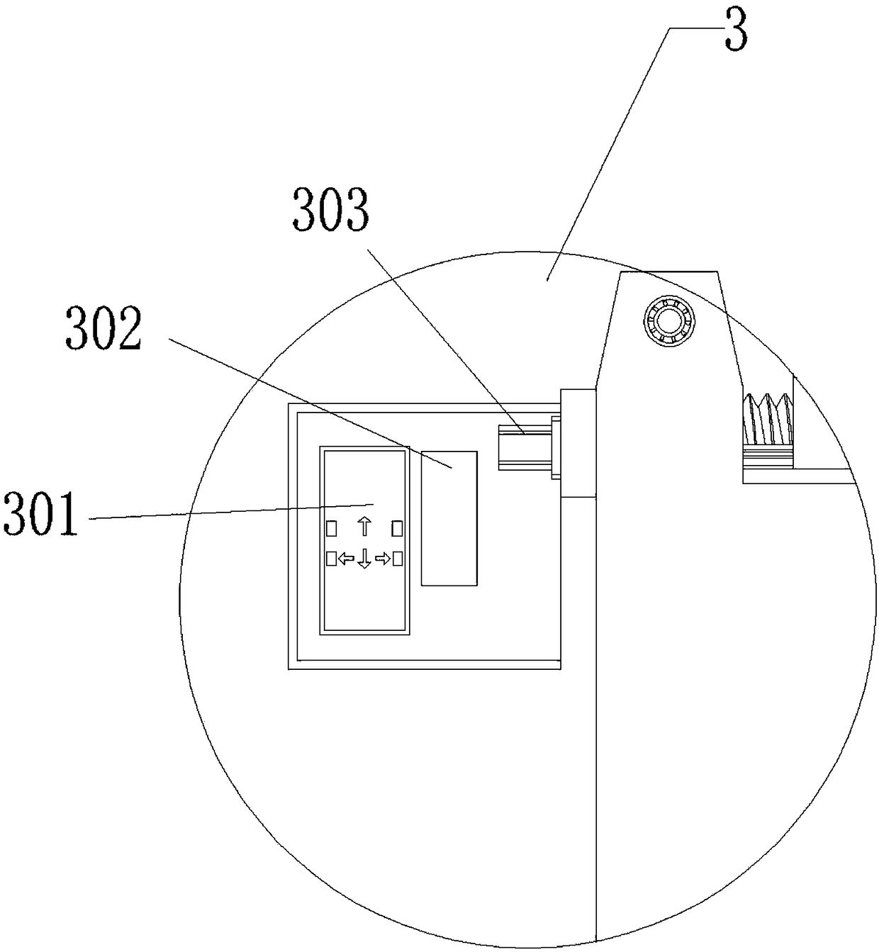
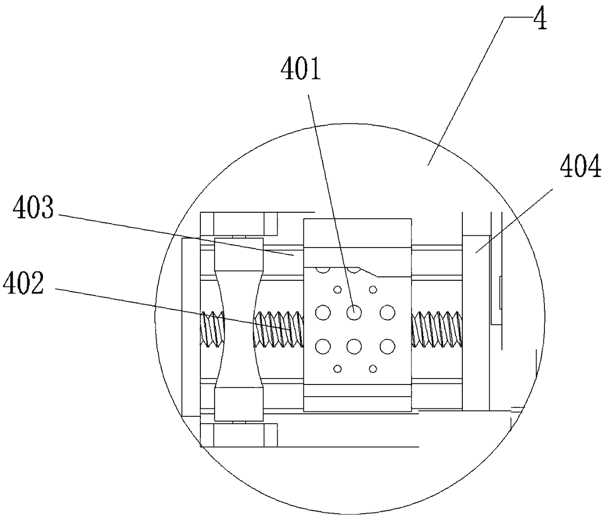
[0041] see Figure 1-12 , the present invention provides a technical solution: an automatic cutting and grinding device, including a body 1, a feeding drive assembly 3, a feeding drive assembly 4, a clamping drive assembly 8, a cutting drive assembly 15, a cutter 18 and a grinding wheel 31, the The feeding drive assembly 3 is arranged below the outer side of the feeding end of the fuselage 1, and two sets of rotating shaft support seats 5 are arranged on the u...


PUM


Abstract

The invention discloses an automatic cutting and polishing device. The automatic cutting and polishing device comprises a machine body, a feeding drive assembly, a feeding transmission assembly, a clamping drive assembly, a cutting drive assembly, a tool and a grinding wheel. The feeding drive assembly is arranged below the outer side of the feeding end of the machine body. The upper parts of thetwo sides of the feeding end of the machine body are provided with two sets of rotating shaft supporting bases, and the two rotating shaft supporting bases are in transmission connection through a bearing and a rotating shaft. The feeding transmission assembly and the machine body are fixedly connected through bolts. A feeding transmission lead screw in the feeding transmission assembly is connected with a feeding motor in the feeding drive assembly through a coupling. One side of a feeding transmission platform on the feeding transmission assembly is connected with a feeding clamping fixing plate through bolts, and the other side of the feeding transmission platform is fixedly connected with a movable baffle through bolts. The outer side of the movable baffle is provided with a clamping movable plate. The end portion of an output shaft of a first oil cylinder in the clamping drive assembly penetrates through the movable baffle to be connected with one side of the clamping movable plate. According to the automatic cutting and polishing device, a pipe fitting is clamped through a cutting clamping fixing block, a first cutting clamping movable block and a second cutting clamping movable block and then is cut, so that the pipe fitting is more stable when a machine vibrates, cutting is smoother, a cross section is smoother, a cooling assembly provides cooling liquid, the machiningprecision is improved, and abrasion of the tool is reduced.

Description

technical field [0001] The invention belongs to the technical field of mechanical processing, and in particular relates to an automatic cutting and polishing device. Background technique [0002] When the pipe fittings are cut, the cutting surface is not smooth enough due to the unstable positioning of the workpiece, and the mechanical vibration generated during the cutting process results in rough cut surfaces with burrs after cutting, which affects the quality of the pipe fittings. The method of manual grinding increases the process of moving back and forth, and the labor cost is large. At the same time, the grinding efficiency is low, the production efficiency is low, and the positioning stability during the grinding process is poor. In view of this, it is necessary to design an automatic grinding device. Contents of the invention [0003] The purpose of the present invention is to provide an automatic cutting and grinding device, which makes the positioning of the work...

Claims


Application Information

Patent Timeline
Patent Type & Authority Applications(China)
IPC IPC(8): B24B5/36B24B27/00B24B41/00B24B41/06
CPCB24B5/36B24B27/0076B24B41/00B24B41/06
Inventor 吴迪贾凯
Owner LIAONING UNIVERSITY OF TECHNOLOGY
Why Eureka
Try Eureka