Microfluidic chips and cell screening methods

A microfluidic chip and target cell technology, applied in chemical instruments and methods, biochemical equipment and methods, animal cells, etc., can solve the problems of low cell efficiency, poor activity, poor sensitivity, etc., and achieve high enrichment efficiency Effect

Active Publication Date: 2020-05-05
晶准生物医学(深圳)有限公司
View PDF3 Cites 0 Cited by
  • Summary
  • Abstract
  • Description
  • Claims
  • Application Information

AI Technical Summary

Problems solved by technology

[0013] The purpose of the present invention is to overcome the above-mentioned deficiencies of the prior art, and provide a microfluidic chip and a cell screening method, aiming to solve the technical problems of low efficiency, poor sensitivity, and poor activity of capturing cells based on microfluidic technology

Method used


Image

  • Microfluidic chips and cell screening methods
  • Microfluidic chips and cell screening methods
  • Microfluidic chips and cell screening methods

Examples


Embodiment 1

[0042] Fabrication of microfluidic chips:

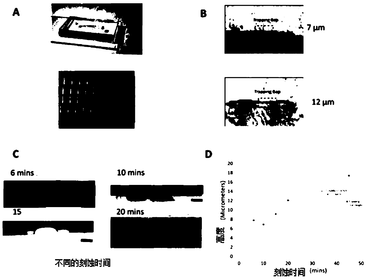
[0043] The microfluidic of this example is fabricated according to soft etching technique, which is formed of polydimethylsiloxane (PDMS) (10:1 silicone rubber and curing agent, Sylgard 184, Dow Midland, MI) combined with printed circuit board (PCB, 75×125×1.6mm, Pty.Ltd.). The microfluidic chip consists of a two-layer structure. The first layer of PDMS is etched on the PCB main board by ferric chloride solution (1.56×10⁻³mol / ml) at different times. The inlet and outlet of the second layer of PDMS are The holes are drilled by a circular hole punch with a diameter of 1.22 mm. The two PDMS layers were treated with air plasma for 2min (plasma cleaner / sterilizer, PPC-3XG, NY,US), and bonded the two PDMS layers together under a microscope.

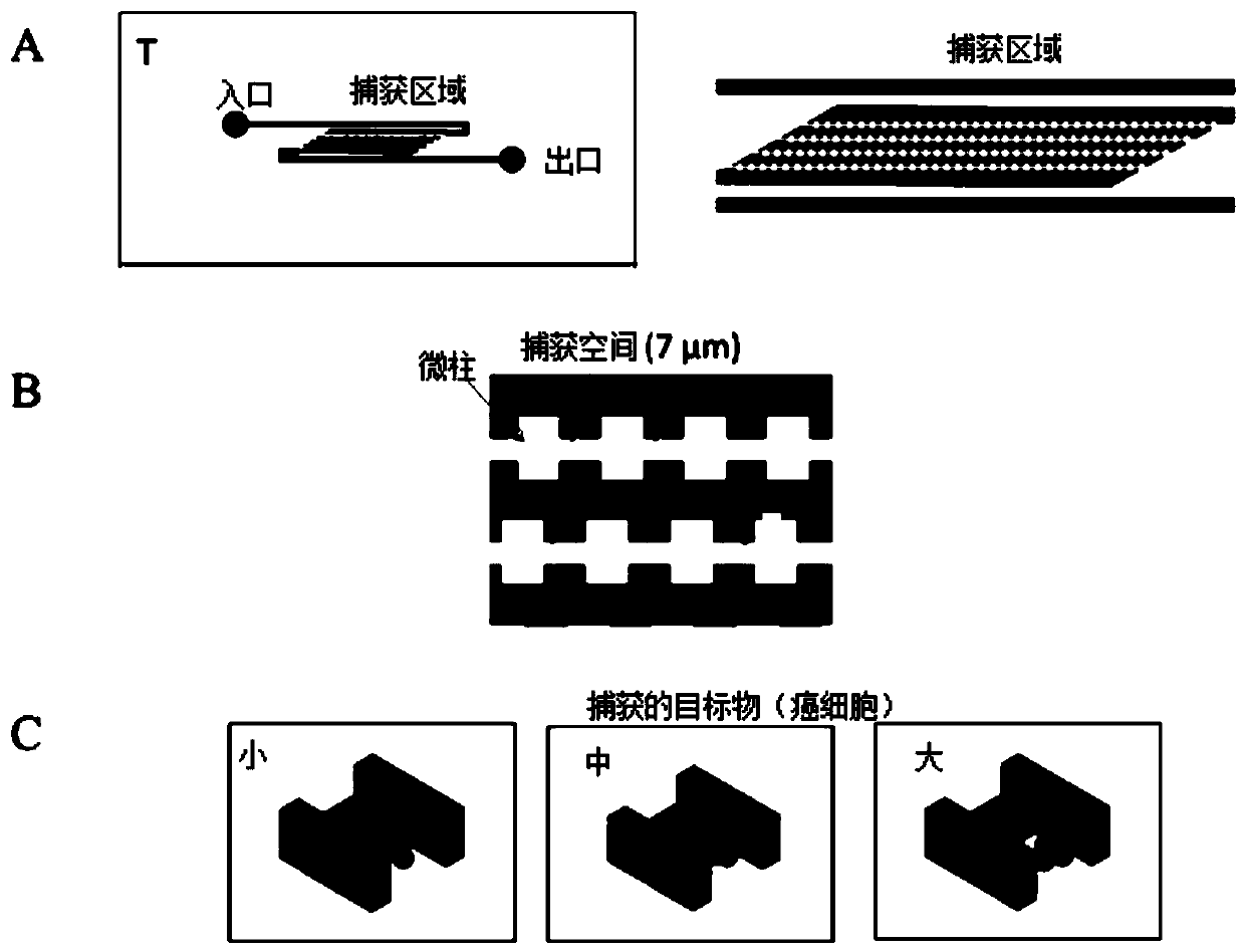
[0044] Our goal is to capture cancer cells through the difference in physical properties between cancer cells and non-cancer cells. Based on the above preparation method, a PDMS microfluidic ch...

Embodiment 2

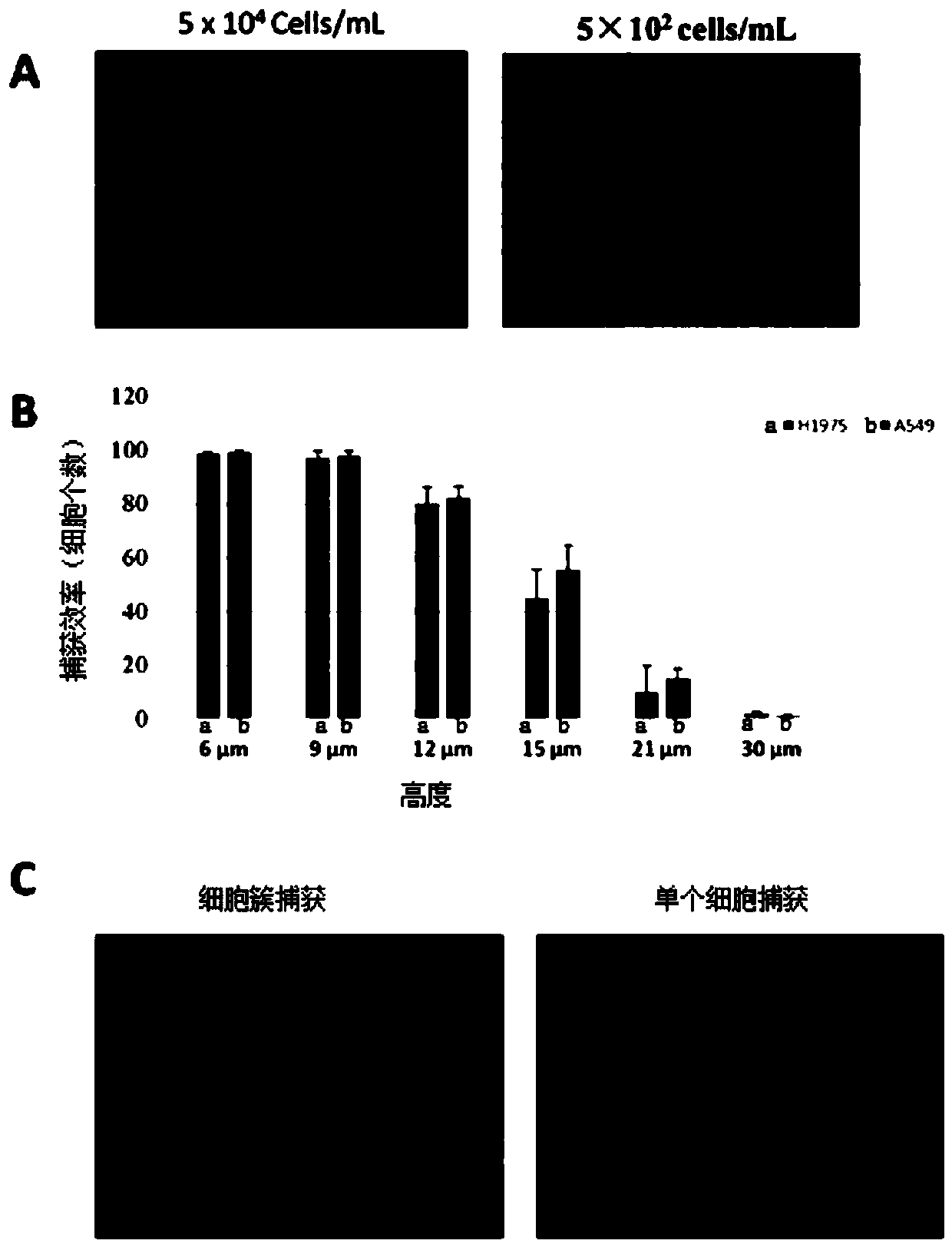
[0048] Non-small cell lung cancer (A549 cells and H1975 cells) are often used to test the feasibility of CTC capture chips. Cancer cells were cultured and suspended using DMEM medium. 1 ml of cell suspensions of different densities were injected from the inlet of the microfluidic chip in Example 1 at a flow rate of 12.5 μL / min through a digital syringe pump. The result is as image 3 as shown, image 3 From the results in A, we can see that almost all single CTC cells can be captured using a chip with a microcolumn height of 7 μm, regardless of the cell density as high as 5×10 4 cells / mL is still as low as 5×10 2 cells / mL. At high cell densities, cancer cells immunostained with red fluorescence were found in all spatially physically captured cells in the chip. Due to the high elasticity of cancer cells, all spatial physical trapping units can find cancer cells at high cell densities. The first row of spatial physical capture cells often has more cells captured because it i...


PUM

PropertyMeasurementUnit
heightaaaaaaaaaa

Abstract

The invention belongs to the technical field of microfluidics, which particularly relates to a microfluidic chip and a cell screening method. The microfluidic chip comprises a substrate and a microfluidic channel positioned in the substrate, wherein a sample inlet and a sample outlet are arranged at the end of the microfluidic channel.A capture unit array is arranged in the microfluidic channel, comprising a plurality of spatial physical capture units. The spatial physical capture unit comprises a capture space between adjacent two microcolumns positioned on the inner wall of the microfluid channel andthe adjacent two microcolumns. The height of the adjacent two microcolumns is smaller than the size of the target substance. When a sample solution containing the target substance is injectedfrom the sample inlet and flows out from the sample outlet, the target substance in the sample solution is embedded in the capture space due to a physical spatial structure.

Description

technical field [0001] The invention relates to the technical field of cell analysis, in particular to a microfluidic chip and a cell screening method. Background technique [0002] Molecular biology and clinical studies have shown that some cancers diagnosed as early stages actually have distant metastases, that is, tumor micrometastases, which are difficult to detect by conventional imaging, histology or cytology methods. Tumor micrometastasis can form micrometastasis lesions in the tissues and organs of the whole body through the hematogenous and lymphatic pathways, and the development of lymph node metastasis will eventually enter the blood circulation to form circulating tumor cells (Circulating Tumor Cells, CTCs), leading to systemic metastasis of the primary tumor. tendency. The detection of CTCs is helpful for early detection of tumor micrometastasis, monitoring of postoperative recurrence, evaluation of curative effect and prognosis, or selection of appropriate ind...

Claims


Application Information

Patent Timeline
Patent Type & Authority Patents(China)
IPC IPC(8): B01L3/00C12N5/09C12Q1/02
CPCB01L3/5027C12N5/0693G01N33/5005
Inventor 陈松峰
Owner 晶准生物医学(深圳)有限公司
Why Eureka
Try Eureka