
Locatable material transfer component

A component and material technology, which is applied in the field of positionable material transfer components, can solve the problems of high management cost, affecting the quality of punching of door pillar panels, and low production efficiency.

Inactive Publication Date: 2019-02-15
GREATOO (GUANGZHOU) ROBOTS & INTELLIGENT MFG CO LTD
View PDF9 Cites 0 Cited by
  • Summary
  • Abstract
  • Description
  • Claims
  • Application Information

AI Technical Summary

Problems solved by technology

The traditional punching and loading of door pillar panels is done manually by workers, and one punching machine corresponds to one operator, which often leads to low production efficiency and high management costs
At present, there is no automatic equipment on the market to replace manual loading. The difficulty lies in the accurate positioning of the workpiece (that is, the door pillar), especially whether the positioning of the workpiece is accurate before being clamped and loaded, which will affect the punching of the door pillar. cut quality

Method used


Image

  • Locatable material transfer component
  • Locatable material transfer component
  • Locatable material transfer component

Examples


Embodiment Construction

[0022] The specific implementation manners of the present invention will be further described in detail below in conjunction with the accompanying drawings and embodiments. The following examples are used to illustrate the present invention, but are not intended to limit the scope of the present invention.

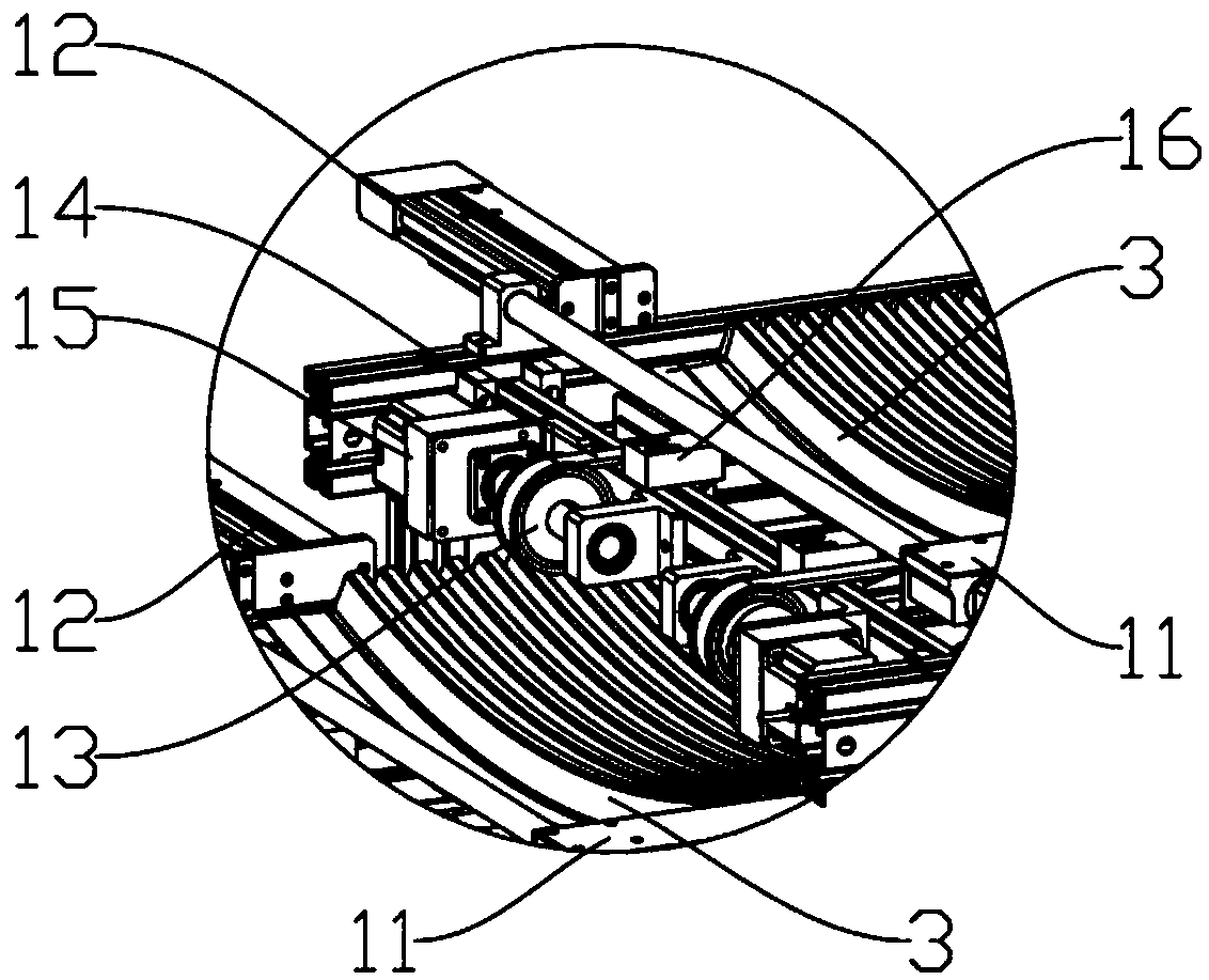
[0023] combine Figure 1 to Figure 6 As shown, the positionable material transfer assembly of the present invention is schematically shown, including a conveying device 1 and a picking device 2 . like figure 2 and image 3 As shown, the conveying device 1 is preferably a belt conveying mechanism, and the belt conveying mechanism includes pulleys 13 located at both ends of the conveying device 1, a conveyor belt 14 wound around the pulley 13, and a first driving device 15 connected to the pulley 13 , the first driving device 15 is made up of a servo motor and a reducer. Under the drive of the first driving device 15, the pulley 13 drives the conveyor belt 14 to move, an...


PUM


Abstract

The invention relates to the field of workpiece conveying, in particular to a locatable material transfer component. A conveying device of the locatable material transfer component can carry and convey a workpiece. One side edge of the conveying device is provided with a limit guide rail and one end of the workpiece movably abuts against the limit guide rail. At the same time, the workpiece and the limit guide can slide relative to each other to realize coarse positioning of the workpiece. When the workpiece is transferred to the tail end of the conveying device, a positioning mechanism startsand pushes one end of the workpiece to force the other end of the workpiece to be tightly attached on the limit guide rail to realize precise positioning of the workpiece. A pickup part of a pickup device is used to pick up the workpiece from the conveying device and transfer the workpiece to the next process.

Description

technical field [0001] The invention relates to the field of workpiece conveying, in particular to a positionable material conveying assembly. Background technique [0002] The door pillar plate is mainly used in the field of automobile door frames, and is one of the important components of the body frame. At present, the door center pillar plate market is mainly made of SPCC cold-rolled carbon thin steel plate, aluminum alloy and other materials. The traditional punching and loading of door pillar panels is done manually by workers, and one punching machine corresponds to one operator, which often results in low production efficiency and high management costs. At present, there is no automatic equipment on the market to replace manual loading. The difficulty lies in the accurate positioning of the workpiece (that is, the door pillar), especially whether the positioning of the workpiece is accurate before being clamped and loaded, which will affect the punching of the door ...

Claims


Application Information

Patent Timeline
IPC IPC(8): B21D43/18B21D43/12B21D43/00
CPCB21D43/003B21D43/12B21D43/18
Inventor 钟俊杰杨惠鑫胡祯曾云郭应斌邓统国林晓驰郑灿杰
Owner GREATOO (GUANGZHOU) ROBOTS & INTELLIGENT MFG CO LTD
Learn More