An integrated program-controlled valve group formed by 3D printing

A technology of 3D printing and program-controlled valve group, which is applied in the direction of multi-way valves, valve devices, valve details, etc., can solve the problem of poor surface performance of the flow channel wall, and achieve a compact structure of the valve area, high safety, and strong reliability Effect

Active Publication Date: 2020-04-21
ZHEJIANG TIANCAIYUNJI TECH CO LTD
View PDF5 Cites 0 Cited by
  • Summary
  • Abstract
  • Description
  • Claims
  • Application Information

AI Technical Summary

Problems solved by technology

[0011] The purpose of the present invention is to propose a brand-new integrated program-controlled valve group formed after the valve area of ​​the adsorption treatment system is integrated, and aim at the existing integrated means in the manufacturing process of the valve area integrated device. The existing problems provide a 3D printing integrated program-controlled valve group, which improves the existing 3D printing technology and solves the integration or integration obtained by the existing integrated and miniaturized design and manufacturing methods. The valve area device still has the problem of poor surface performance of the flow channel wall after molding

Method used


Image

  • An integrated program-controlled valve group formed by 3D printing
  • An integrated program-controlled valve group formed by 3D printing
  • An integrated program-controlled valve group formed by 3D printing

Examples


Embodiment 1

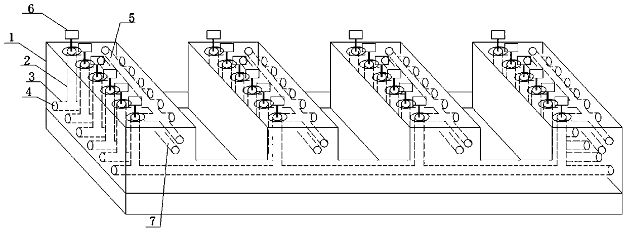
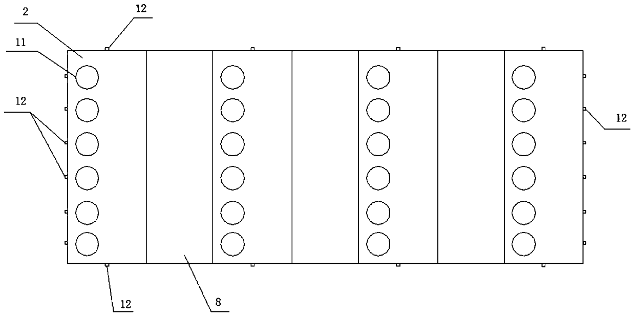
[0081] This embodiment provides an integrated program-controlled valve group for the problem that the valve area of ​​the existing adsorption treatment system is too large and is not convenient for integrated skid-mounted design, specifically including: the valve group body; the valve group body is set There are several unit blocks 1, and the bottom is provided with several converging flow channels 3 that pass through the unit blocks 1 left and right; the unit block 1 is provided with an inlet flow channel 7 and an outlet flow channel 5 that pass through the unit block 1 front and rear, and A plurality of branch channels 2 corresponding one-to-one to the converging channel 3; one end of each of the branch channels 2 is communicated with the outlet channel 5, and the other end is in communication with the corresponding converging channel 3, and each of the branch channels Channels 2 are provided with controllable valves 6; the surface of the unit block 1 is provided with opening...

Embodiment 2

[0106] An integrated program-controlled valve group formed by 3D printing, comprising the following steps:

[0107] 1) Raw material preparation: According to the needs of the integrated program-controlled valve group, prepare skeleton materials, permeable materials and support materials;

[0108] 2) Printing and molding: use a multi-nozzle 3D printer to print layer by layer according to the shape and size of the integrated program-controlled valve group, and form a preliminary molded part; each layer is made of skeleton material, permeable material and support material. one or more of the constituents of

[0109] 3) Part sintering: the preliminary shaped part obtained in step 2 is preheated, supported material consolidated, carburized, quenched and tempered to obtain a sintered shaped part;

[0110] 4) Part cleaning: After blowing off the pyrolysis residues and ultrasonic water washing of the sintered shaped part obtained in step 3, the shaped part is obtained.

[0111] Wher...

Embodiment 3

[0125] An integrated program-controlled valve group formed by 3D printing, comprising the following steps:

[0126] 1) Raw material preparation: According to the needs of the integrated program-controlled valve group, prepare skeleton materials, permeable materials and support materials;

[0127] 2) Printing and molding: use a multi-nozzle 3D printer to print layer by layer according to the shape and size of the integrated program-controlled valve group, and form a preliminary molded part; each layer is made of skeleton material, permeable material and support material. one or more of the constituents of

[0128] 3) Part sintering: the preliminary shaped part obtained in step 2 is preheated, supported material consolidated, carburized, quenched and tempered to obtain a sintered shaped part;

[0129] 4) Part cleaning: After blowing off the pyrolysis residues and ultrasonic water washing of the sintered shaped part obtained in step 3, the shaped part is obtained.

[0130] Wher...


PUM

PropertyMeasurementUnit
particle diameteraaaaaaaaaa
melting pointaaaaaaaaaa

Abstract

The invention discloses an integrated program-controlled valve group formed by 3D printing. By utilizing the advantages of fast and accurate molding of 3D printing technology, an integrated program-controlled valve group with its own internal integrated flow channel is obtained. Pipelines and valve components are integrated in the integrated program-controlled valve group in the form of unit blocks, so that the on-site valve area of ​​the adsorption treatment system has a compact structure and reduced volume, which is convenient for modularization, skid-mounting, equipment and vehicle-mounting; at the same time, For this integrated program-controlled valve group, a new 3D printing molding process combining "printing molding + infiltration process + sintering process" is provided, which combines the characteristics of 3D printing rapid prototyping, and makes the inner wall surface of the complex flow channel after the part is formed. It is smooth and has excellent anti-wear and anti-cavitation capabilities, which completely solves the difficulties in processing and forming when the flow channel integration is too high during the skid-mounted design process of the valve area of ​​the adsorption treatment system and the flow channel wall after forming. The problem of poor surface properties.

Description

technical field [0001] The invention relates to the field of integrated control valve groups, in particular to an integrated program-controlled valve group formed by 3D printing. Background technique [0002] With the continuous development and progress of industries such as semiconductors and hydrogen fuel cells, the market demand for high-purity gases including hydrogen and ammonia is increasing, and the quality requirements are also getting higher and higher. In addition, due to the high cost and low utilization rate of the high-purity gas used, the separation, purification, recovery and reuse of the corresponding gas has also become one of the focuses of enterprises. [0003] As the most effective gas deep separation and purification technology at present, temperature swing adsorption and pressure swing adsorption, both of which use molecular sieves carrying gas adsorbates to have different adsorption properties for different gas molecules under different temperature or ...

Claims


Application Information

Patent Timeline
Patent Type & Authority Patents(China)
IPC IPC(8): F16K11/22F16K27/00B22F3/105B29C64/165B33Y10/00B33Y80/00
CPCF16K11/22F16K27/00B29C64/165B33Y10/00B33Y80/00B22F10/00B22F10/28B22F10/64B22F10/43B22F12/55B22F10/68B22F12/53Y02P10/25
Inventor 陈运刘开莉钟雨明蔡跃明
Owner ZHEJIANG TIANCAIYUNJI TECH CO LTD
Why Eureka
Try Eureka