Planar phased array antenna

An array antenna and planar phase technology, which is applied in the field of lightweight planar phased array antennas, can solve problems such as the inability to meet the requirements of heat dissipation and light weight, and achieve the effect of expanding light weight and good heat dissipation.

Inactive Publication Date: 2019-02-01
BEIJING INST OF RADIO MEASUREMENT
View PDF4 Cites 8 Cited by
  • Summary
  • Abstract
  • Description
  • Claims
  • Application Information

AI Technical Summary

Problems solved by technology

There are strict size and weight restrictions on the lightweight planar phased array antenna as a whole. However, for the current lightweight planar phased array antenna, the cooling design with a calorific value below 10kW cannot meet both the heat dissipation requirements and the The need for lightweight

Method used


Image

  • Planar phased array antenna
  • Planar phased array antenna
  • Planar phased array antenna

Examples


Embodiment 1

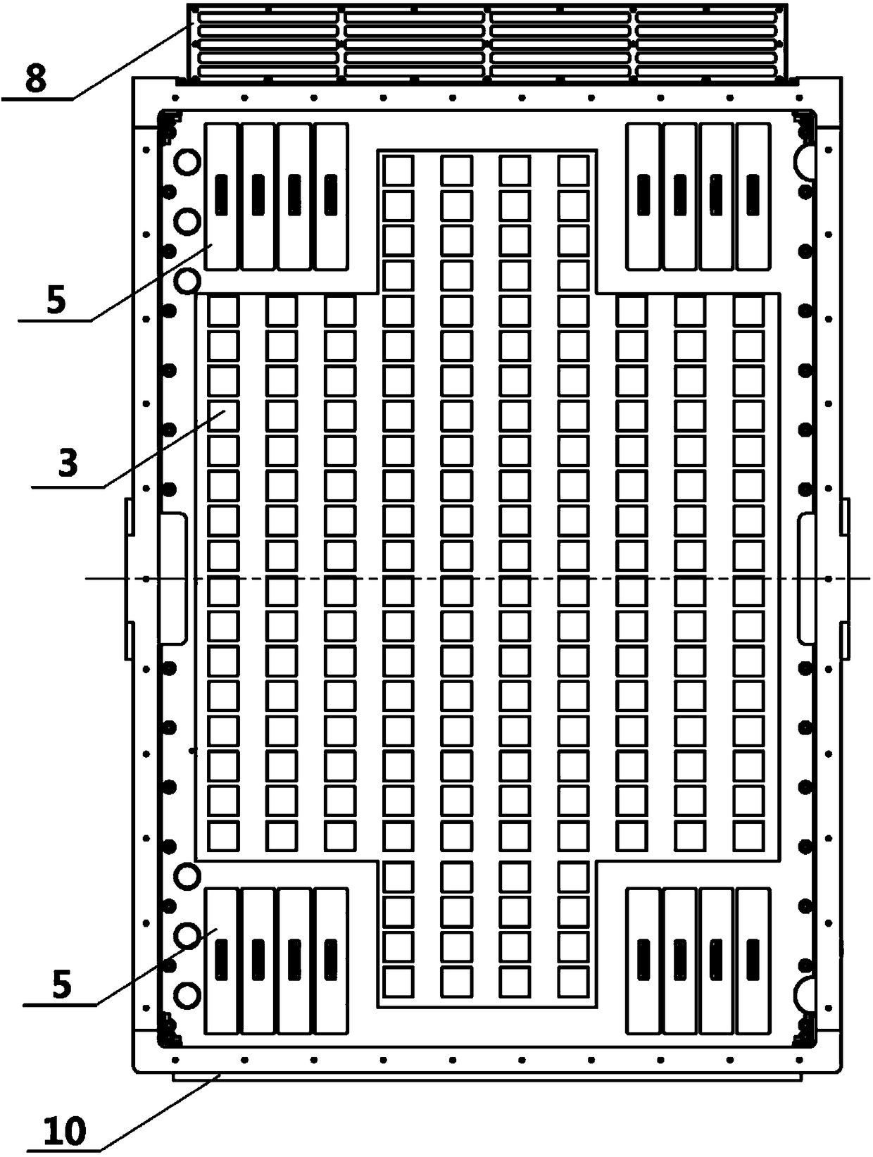
[0028] Such as figure 1 As shown, this example discloses a planar phased array antenna, which can directly use the heat dissipation device to cooperate with the air duct formed between the internal components of the antenna frame 1 and the module mounting frame 6 to dissipate heat from the heating device inside the antenna. There is no need to add additional cooling air ducts, which greatly saves the space used inside the antenna, and makes the antenna lighter and smaller while ensuring the cooling effect.

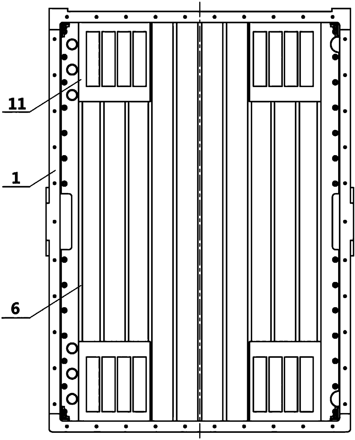
[0029] Specifically, the antenna includes: an array panel 2 and a plurality of antenna units 3 arranged oppositely on the antenna frame 1 . The antenna frame 1 is a rectangular hollow frame, the array panel 2 is fixed inside the antenna frame 1 through the array frame, and a plurality of antenna units 3 are arranged in an array and fixed on the opposite side of the array panel 2 through the module mounting frame 6 . The inside of the antenna frame 1 is provided with a plu...

Embodiment 2

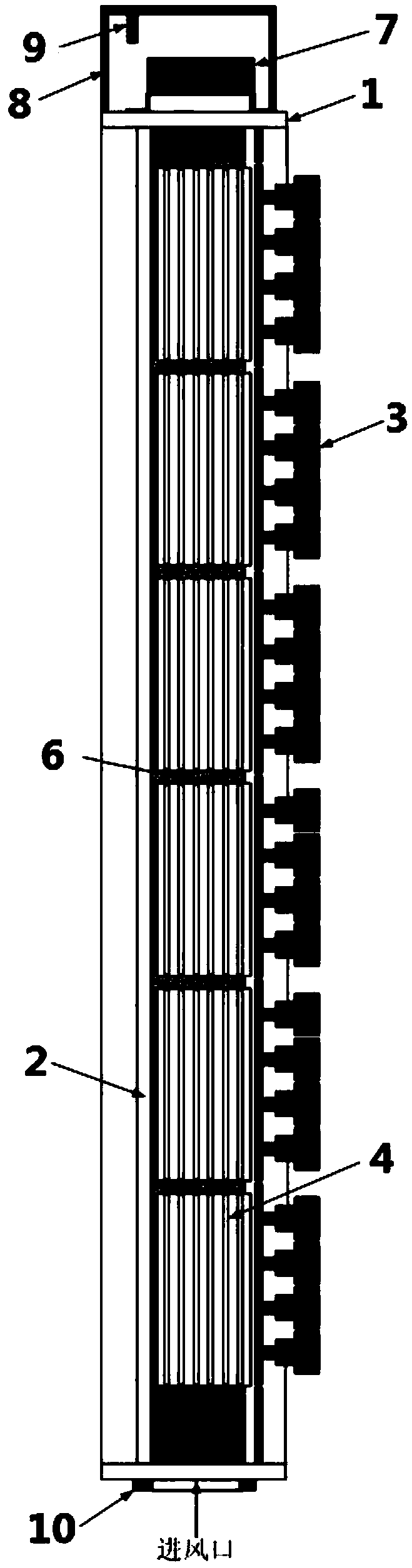
[0037] Such as figure 1 and image 3 As shown, a light-weight planar phased array antenna is disclosed, which mainly includes: antenna frame 1, antenna unit 3, module mounting frame 6, TR assembly 4, power supply assembly 5, fan assembly 7, windshield 8, Downwind cover 10, cover plate 11, temperature sensor 9 and other parts.

[0038] The TR component 4 and the power supply component 5 in the antenna are the main heat generating components, therefore, the key measures for heat dissipation are mainly carried out for the above two components. In this embodiment, when designing the TR assembly 4 and the power supply assembly 5, the air-cooled heat sink 12 is integrally processed and formed with the shells of the TR assembly 4 and the power supply assembly 5; at the same time, the TR assembly 4 and the power supply assembly The heat source of 5 is closely attached to the base of the heat sink 12, and a layer of heat-conducting silicone grease gasket is installed on the bonding s...


PUM


Abstract

The embodiment of the invention provides a planar phased array antenna. The antenna comprises an array panel and a plurality of antenna units which are arranged on an antenna frame; the antenna frameis internally provided with a plurality of module installation racks configured to fix more than one type of a TR module, a power module and the antenna units; the top end of the antenna frame is provided with a cooling device; the cooling device is cooperated with a plurality of air flow circulation channels formed among the plurality of module installation racks to perform heat radiation for theplanar phased array antenna. The cooling device is cooperated with a plurality of air flow circulation channels formed among the plurality of module installation racks to exhaust the heat of the heating device led out through cooling fins out of the antenna to allow the antenna to be better in heat radiation, lighter in weight and mini-type without change of the whole structure of the antenna andfurther expand the light-weight and mini-type application of a radar weapon system.

Description

technical field [0001] The present application relates to the field of antenna heat dissipation, in particular to a light-weight planar phased array antenna with a combined heat dissipation structure. Background technique [0002] With the continuous improvement of the combat radius and phase scanning range of the radar antenna, the radiated power of the antenna unit 3 is getting larger and larger, which makes the power of active components such as TR components and power components higher and higher. In order to make the radar antenna work normally, these Heating components need to be cooled in time. In the field of radar, there are two commonly used cooling methods: air cooling and water cooling. Generally, air cooling can be used for heat dissipation below 10kW, and water cooling is required for heat dissipation above 10kW. There are strict size and weight restrictions on the lightweight planar phased array antenna as a whole. However, for the current lightweight planar ...

Claims


Application Information

Patent Timeline
Patent Type & Authority Applications(China)
IPC IPC(8): H01Q1/00H01Q1/12
CPCH01Q1/02H01Q1/12
Inventor 关楠楠曹保忠
Owner BEIJING INST OF RADIO MEASUREMENT
Why Eureka
Try Eureka