
Economical water tank dedusting reversing fan device

An economical, water tank technology, applied in the direction of non-variable pumps, engine components, machines/engines, etc., can solve the problems of difficulty in manual dust removal, unfavorable processing and production, and easy formation of dust and other problems, so as to solve the problem of long-term exposure and facilitate Processing and production, the effect of simple structure of the whole machine

Inactive Publication Date: 2019-01-25
孙浩
View PDF5 Cites 0 Cited by
  • Summary
  • Abstract
  • Description
  • Claims
  • Application Information

AI Technical Summary

Problems solved by technology

[0003] At present, in the solution of the dust accumulation on the cooling fins of the engine water tank, artificial air guns and water guns are generally used to remove dust from the cooling fins. This method can only remove a small amount of dust accumulation, and the effect is acceptable for the field where the dust accumulation is not obvious. , but there is also the problem that if the dust is not removed in time, it is easy to form dust, which makes it difficult to remove it during manual dust removal; especially in the fields of high pollution and heavy dust in agriculture and industry, the heat sink of the engine water tank is particularly easy to accumulate Dust, only manual dust removal is not only inefficient and not timely, but also seriously affects the heat dissipation efficiency of the engine, affects the working performance of the engine and even affects the service life of the engine
[0004] In the Chinese Patent Publication No. CN206530397U, the solution mentioned has a process of spring return drive. In the above disclosed patent documents, the spring return device is arranged outside the shell, which is prone to corrosion in the open environment for a long time. Reset performance; the most important thing is that in the existing technical solutions, when the fan blades are in the state of reverse dust removal, the return spring is often compressed strongly, and at this time the blades are also rotated at a certain angle for reverse blowing. In practical applications, it is found that At this time, the spring is in the state of maximum energy storage, coupled with the reaction force of reverse blowing, it is often easy to push the fan backwards away from the radiator of the water tank, resulting in poor dust removal effect of the radiator. The existing structure is in the state of heat dissipation and dust removal. The distance between the fan blade and the radiator changes greatly. Due to the drive of the reversing device and the drive of the reset device, if fatigue occurs after long-term use, the parts cannot be completely reversed and reset. The effect on heat dissipation and dust removal is The third is that the existing product structure is complex, which is not conducive to processing and production, and the shell also needs to move left and right during work, which also has great impact on mechanical safety. big potential risk

Method used


Image

  • Economical water tank dedusting reversing fan device
  • Economical water tank dedusting reversing fan device
  • Economical water tank dedusting reversing fan device

Examples


Embodiment 1

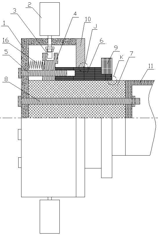
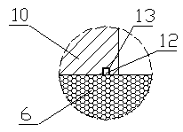
[0016] Embodiment 1: as figure 1 , image 3 and Figure 4 As shown, a new type of water tank dust removal reversing fan device includes a housing 1, blades 2, small shift fork 3, center positioning gear 4, spring 16, guide rod 5, transmission sleeve 6, central shaft 7, main bearing 9 and shell Cover 10; the outer circumference of the housing 1 is provided with blades 2, the blades 2 pass through the housing 1 and are fixedly connected with the small shift fork 3, the small shift fork 3 is in movable contact with the center positioning gear 4, and the center positioning The right side of the gear 4 is fixedly connected to the transmission sleeve 6, and the center positioning gear 4 and the transmission sleeve 6 are provided with guide holes at corresponding horizontal positions, and the guide rod 5 is fixed to the housing 1 and slides sequentially through the guide holes Connected to the central positioning gear 4 and the transmission sleeve 6, the central positioning gear 4 ...

Embodiment 2

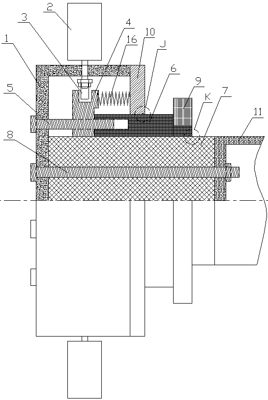
[0017] Embodiment 2: as figure 2 , image 3 and Figure 4 As shown, a new type of water tank dust removal reversing fan device includes a housing 1, blades 2, small shift fork 3, center positioning gear 4, spring 16, guide rod 5, transmission sleeve 6, central shaft 7, main bearing 9 and shell Cover 10; the outer circumference of the housing 1 is provided with blades 2, the blades 2 pass through the housing 1 and are fixedly connected with the small shift fork 3, the small shift fork 3 is in movable contact with the center positioning gear 4, and the center positioning The right side of the gear 4 is fixedly connected to the transmission sleeve 6, and the center positioning gear 4 and the transmission sleeve 6 are provided with guide holes at corresponding horizontal positions, and the guide rod 5 is fixed to the housing 1 and slides sequentially through the guide holes Connected to the central positioning gear 4 and the transmission sleeve 6, the central positioning gear 4...


PUM


Abstract

The invention discloses an economical water tank dedusting reversing fan device. The economical water tank dedusting reversing fan device comprises a shell, blades, a small shifting force, a central positioning gear, an elastic device, a guide rod, a transmission sleeve, a central shaft, a main bearing and a shell cover. The economical water tank dedusting reversing fan device has the advantages that by a combined coordination manner using the shell as the fixed part and the central positioning gear as the movable part, the problem of radiating and dedusting performance instability caused by distance change between the blades and a radiator in a normal and reversing process, and fixed-distance radiating and dedusting between the blades and the radiator is achieved; by a built-in spring, the problem of long-term spring exposure is solved, the service life of a resetting mechanism is guaranteed while the whole device is compact and small in overall structure, and the safety of a mechanical moving part is improved; the whole device is simple in structure and convenient to produce, production cost is lowered greatly, and the device can be popularized and used favorably.

Description

[0001] This application is a divisional application of a novel water tank dedusting and reversing fan device. The filing date of the original application is February 14, 2018, the application number is 201810151822.8, and the name of the invention is a new type of water tank dust removal reversing fan device. technical field [0002] The invention relates to the technical field of dust removal devices, in particular to an economical water tank dust removal reversing fan device. Background technique [0003] At present, in the solution of the dust accumulation on the cooling fins of the engine water tank, artificial air guns and water guns are generally used to remove dust from the cooling fins. This method can only remove a small amount of dust accumulation, and the effect is acceptable for the field where the dust accumulation is not obvious. , but there is also the problem that if the dust is not removed in time, it is easy to form dust, which makes it difficult to remove ...

Claims


Application Information

Patent Timeline
Patent Type & Authority Applications(China)
IPC IPC(8): F01P5/02F01P11/06F04D19/00
CPCF01P5/02F01P11/06F01P2011/063F04D19/005
Inventor 孙浩
Owner 孙浩
Learn More