Packing box punching tool plate

A packaging box and punching technology, used in metal processing and other directions, can solve the problems of arching and burrs of printed matter, die-cutting failure, increased contact surface and friction, etc., and achieve the effect of improving die-cutting quality and die-cutting stability.

Pending Publication Date: 2019-01-25
浙江大洪包装科技股份有限公司
View PDF0 Cites 0 Cited by
  • Summary
  • Abstract
  • Description
  • Claims
  • Application Information

AI Technical Summary

Problems solved by technology

[0003] Generally, the unfolded surface of the printed matter is relatively large, and the surface is relatively smooth. During die-cutting and root processing, the cutting knife body and the indentation knife body tend to slide, resulting in slight arching of the die-cutting surface of the printed matter, resulting in deviations in die-cutting. Even cause the product to be scrapped
[0004] In addition, in the process of lifting the knife body from the printed matter after cutting into the printed matter, the contact surface and friction between the knife body and the printed matter increase due to the length of the knife body. Arching and burrs are aggravated, and even the printed matter cannot be conveyed normally after being taken up, resulting in die-cutting failure or product scrap;
[0005] In addition, the die-cutting knife plate often needs to be typeset according to the printed matter. In many cases, the distribution of the knife is often not in the middle of the plate body, which causes the plate body to tilt due to uneven force during the die-cutting process, resulting in rough edges of the incision. Aggravation and incision misalignment

Method used


Image

  • Packing box punching tool plate
  • Packing box punching tool plate

Examples


Embodiment Construction

[0019] In order to make the purpose, technical solutions and advantages of the present application clearer, the technical solutions in the embodiments will be clearly and completely described below in conjunction with the accompanying drawings in the embodiments,

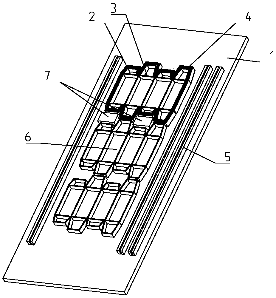
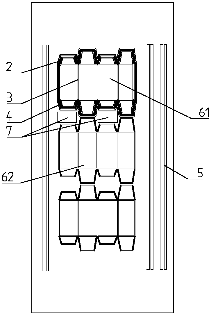
[0020] A packaging box stamping knife plate, including a plate body 1, a plurality of die-cut blocks according to the typesetting of the packaging box, the die-cut blocks include a cutting knife body 2 and an indentation knife body 3 fixed on the plate body 1, this embodiment Among them, the die-cutting block is divided into a first die-cutting block 61 and a second die-cutting block 62 (the second die-cutting block 62 is a cutting knife body 2 and an indentation knife body 3 without an elastic pad 4 in the prior art, so as to facilitate Compared with the strokes of the cutting knife body 2 and the creasing knife body 3 placed with elastic pads), the arrangement of the cutting knife body 2 and the creasing knife body...


PUM


Abstract

The invention discloses a packing box punching tool plate, comprising a plate body and a plurality of die cutting blocks arranged according to a packing box. The die cutting blocks comprise a cutting-off tool and an indenting tool both fixed to the plate body; the cutting-off tool and the indenting tool are arranged according to the structure of the packing box. The packing box punching tool plateis characterized in that an elastic pad is fixed to each side of each cutting-off tool on the plate body, the thickness of the elastic pads is not less than the height of the cutting-off tools, elastic strips are compressed during die cutting and may restore and generate elastic force after die cutting is complete and when the cutting-off tools are lifted up, and the elastic force helps pop awaya printed product and separate from the tools; in addition, the elastic strips enable die cutting to be more stable and are higher than the tools, so that the elastic strips gain contact first with the printed product during de cutting, die cutting is more stable, and die cutting quality of the printed product is improved.

Description

technical field [0001] The invention belongs to the technical field of packaging box production equipment, and in particular relates to a punching knife plate for packaging boxes. Background technique [0002] The die-cutting process is the most commonly used process for packaging printed matter. It is to use a die-cutting knife to form a die-cutting plate according to the pattern required by the product design. Cutting molding process. The indentation process is to use a creasing knife or a creasing die to press the line marks on the sheet through the action of pressure, or use a rolling wheel to bend and shape the sheet at a predetermined position. Generally, the die-cutting and creasing process is a process in which the die-cutting knife and the creasing knife are combined in the same template, and the die-cutting and creasing are performed on the die-cutting machine at the same time, which is called die-cutting for short. [0003] Generally, the unfolded surface of the...

Claims


Application Information

Patent Timeline
IPC IPC(8): B26F1/44
CPCB26F1/44B26F2001/4418
Inventor 奚晓亮詹诗光
Owner 浙江大洪包装科技股份有限公司
Why Eureka
Try Eureka