
Eureka
For R&D, Eureka makes reading and utilizing patents & technical documents easy.
Eureka AIR
Designed for self-driven R&D workflows. Generate viable solutions, solve complex R&D challenges, empower your innovation with AI.

Eureka Materials
Designed for material experts only. Revolutionize your material R&D, from search, analyze, to developing new materials.

TechResearch
Generate reliable direction feasibility study reports for your R&D in just a few steps.

TechSeek
Discover and master advanced knowledge NOW. Basics, ideas, possibilities, all at once.

TechMind
As an expert in R&D Theories, TechMind can generates customized viable solutions instantly.

TechRisk
Analyze your overall solution with one click, know your potential R&D risks in advance.

TechMonitor
Get weekly tech updates, stay abreast of the latest tech innovations and key insights.
A thermally superconducting plate and a method of manufacturing the same
A technology of thermal superconductivity and deflectors, which is applied in the field of heat transfer, can solve the problems that aluminum radiators cannot meet the heat dissipation requirements of high heat flux density and high-power modules, and achieve enhanced thermal superconducting heat dissipation capabilities, large heat dissipation capabilities, and high heat dissipation. small resistance effect
- Summary
- Abstract
- Description
- Claims
- Application Information
AI Technical Summary
Problems solved by technology
Method used
Image

Examples
Embodiment 1
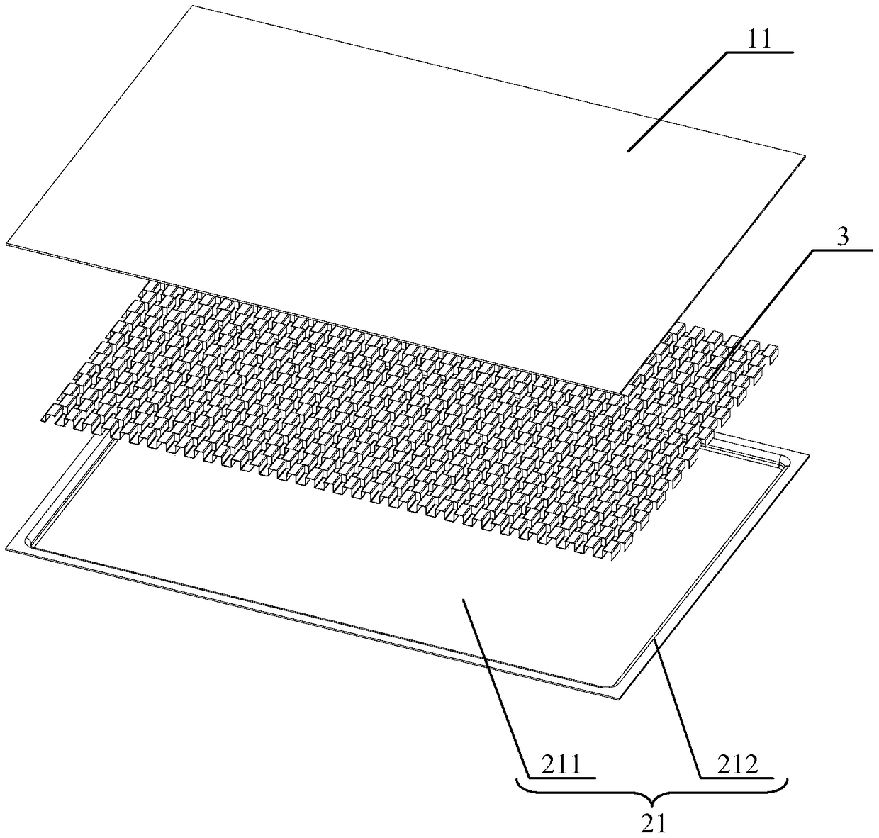
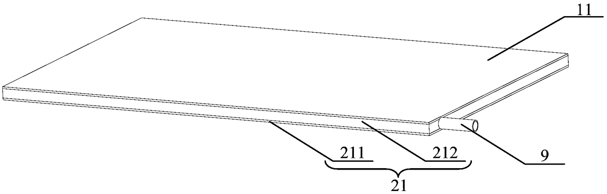
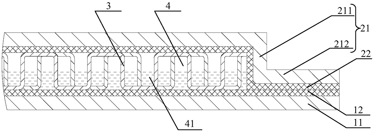
[0089] see Figure 1 to Figure 9 , the present invention provides a thermal superconducting plate, the thermal superconducting plate includes: a first cover 11, a second cover 21 and at least one deflector 3; wherein, the second cover 21 includes a cover The main body 211 and the annular convex edge 212, the annular convex edge 212 is integrally connected with the cover plate main body 211; the first cover plate 11 is placed on the surface of the annular convex edge 212 away from the cover plate main body 211 , to form a sealed chamber (not shown) between the first cover plate 11 and the cover plate main body 211; the deflector 3 is located in the sealed chamber, and the deflector 3 includes several a convex portion 31 arranged at intervals along the first direction and extending along the second direction, wherein the first direction is perpendicular to the second direction, and the bottom of the convex portion 31 is adjacent to the first direction Integral connection, and t...
Embodiment 2
[0103] Please combine Figure 1 to Figure 9 refer to Figure 10 to Figure 14 , this embodiment also provides a thermal superconducting plate. The structure of the thermal superconducting plate described in this embodiment is roughly the same as that of the thermal superconducting plate described in Embodiment 1. The difference between the two lies in: this Compared with the thermal superconducting plate described in Embodiment 1, the thermal superconducting plate described in the embodiment is provided with at least one reserved gap 34 in the deflector 3, and at the same time, the thermal superconducting plate also At least one pad 6 is included or at least one stamping boss 8 is provided on the first cover 11 or the second cover 21 . Other structures of the thermal superconducting plate described in this embodiment are identical to those of the thermal superconducting plate described in Embodiment 1. Please refer to Embodiment 1 for details, and will not be repeated here.
...
Embodiment 3
[0108] Please combine Figure 1 to Figure 13 refer to Figure 15 and Figure 16 , this embodiment also provides a thermal superconducting plate. The structure of the thermal superconducting plate described in this embodiment is roughly the same as that of the thermal superconducting plate described in Embodiment 1. The difference between the two lies in: implementing The number of deflectors 3 described in the thermal superconducting plate described in Example 1 is one, while the number of deflectors 3 described in this embodiment is at least two, and the adjacent said deflectors 3, there is a gap between them, so as to form the first balance channel 51 of the heat transfer working medium 41 between the adjacent deflectors 3, and the first balance channel 51 extends along the first direction, that is, the The extension direction of the first balancing channel 51 is parallel to the first direction. Other structures of the thermal superconducting plate described in this embod...
PUM
 Abstract
Description
Claims
Application Information
 - R&D Engineer
- R&D Manager
- IP Professional
- Industry Leading Data Capabilities
- Powerful AI technology
- Patent DNA Extraction
Browse by: Latest US Patents, China's latest patents, Technical Efficacy Thesaurus, Application Domain, Technology Topic, Popular Technical Reports.
© 2024 PatSnap. All rights reserved.Legal|Privacy policy|Modern Slavery Act Transparency Statement|Sitemap|About US| Contact US: help@patsnap.com