
Multi-effect screening device

A sieving device and sieving machine technology, applied in sieving, grading, solid separation, etc., can solve the problems of sieve rollers not being washed, high speed of sieve rollers, and single function, so as to improve the overall life and prolong the service life , the effect of no power plant

Inactive Publication Date: 2019-01-18
肖忠义
View PDF0 Cites 0 Cited by
  • Summary
  • Abstract
  • Description
  • Claims
  • Application Information

AI Technical Summary

Problems solved by technology

[0003] Both too good and too bad screening efficiency will bring certain unfavorable factors
[0004] 1. If the screening efficiency is too good, it will lead to: 1. The high rotating speed of the screening roller will bring unnecessary power consumption and increase the mechanical wear of the screening roller and transmission equipment.
2. Because the screening efficiency is too high, the material has already been screened when it passes through the upper screen roller, so the lower screen roller cannot be washed by new materials, and debris is easy to accumulate in the gap
The sundries will accumulate between the sieve roll gaps for a long time, resulting in abnormal wear of this part of the sieve rolls
[0005] 2. Too low screening efficiency will lead to: the whole roller screening machine cannot be screened, and cannot meet the normal pellet production needs
[0006] The conveyor belt and screening device are generally set separately, with complex structure and single function

Method used


Image

  • Multi-effect screening device
  • Multi-effect screening device
  • Multi-effect screening device

Examples


Embodiment Construction

[0027] The following will clearly and completely describe the technical solutions in the embodiments of the present invention with reference to the accompanying drawings in the embodiments of the present invention. Obviously, the described embodiments are only some, not all, embodiments of the present invention. Based on the embodiments of the present invention, all other embodiments obtained by persons of ordinary skill in the art without making creative efforts belong to the protection scope of the present invention.

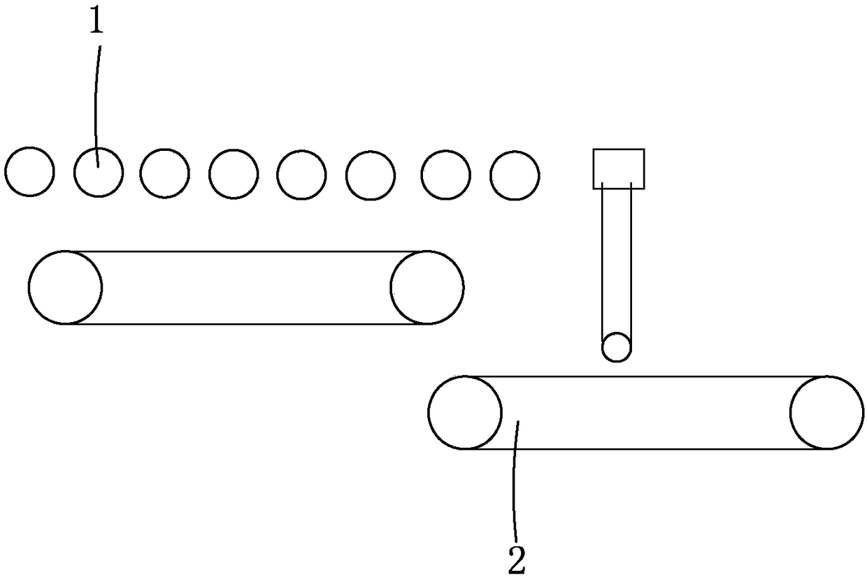
[0028] see figure 1 , figure 1 It is a structural schematic diagram of a preferred embodiment of the multi-effect screening device provided by the present invention.

[0029] The multi-effect screening device includes a real-time controllable self-cleaning roller screening machine 1 and a conveyor belt screening device 2 . The conveyor belt screening device 2 is located relatively in front or behind the real-time controllable self-cleaning roller screening m...


PUM


Abstract

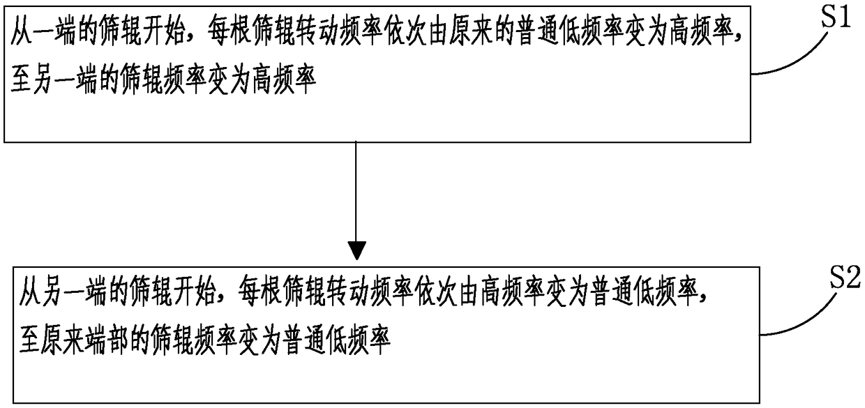
The invention provides a multi-effect screening device. The multi-effect screening device comprises a real-time controllable self-cleaning roller screening machine; the real-time controllable self-cleaning roller screening machine comprises a plurality of screening rollers, a screening roller motor, a motor frequency converter and a programmable logic controller control program; the programmable logic controller control program controls the screening roller motor with the following specific steps: (1) starting from the screening roller at one end, changing the rotating frequency of each screening roller from the original ordinary low frequency to high frequency in sequence, and then changing the rotating frequency of the screening roller at the other end to high frequency; (2) starting from the screening roller at the other end, changing the rotating frequency of each screening roller from high frequency to ordinary low frequency in sequence, and then changing the frequency of the screening roller at the original end to ordinary low frequency. The multi-effect screening device utilizes the rotative speed difference of the two screening rollers to clear up the impurities between thescreening rollers, achieving the circulation of cleaning the impurities between the screening rollers, timely adjusting the circulation period of cleaning according to the amount of materials and impurities, ensuring no impurities between the screening roller gaps are accumulated for long term, and extending the service life of the screening roller.

Description

technical field [0001] The invention relates to the field of screening device equipment, in particular to a multi-effect screening device. Background technique [0002] Roller sieving machine is a special equipment for sieving ungraded mixed balls that are excluded from pelletizing machines. It has been widely used in iron and steel, metallurgy and chemical industries. The n screen rollers rotate to classify the spherical materials. At present, the rotating speed of the sieve roller of the roller sieving machine is fixed. Due to the production volume and the nature of the screened material vary. The fixed speed roller screening machine cannot adjust the screening efficiency in real time according to the production situation at that time. Bring great passiveness to pellet production. [0003] Both too good and too bad screening efficiency will bring certain unfavorable factors. [0004] 1. If the screening efficiency is too good, it will lead to: 1. The high speed of the...

Claims


Application Information

Patent Timeline
IPC IPC(8): B07B15/00B07B1/14B07B1/42B07B13/05B07B13/14
CPCB07B15/00B07B1/14B07B1/42B07B13/05B07B13/14
Inventor 肖忠义
Owner 肖忠义
Learn More