AMT intermediate shaft braking structure

An intermediate shaft and brake disc technology, applied in the direction of brake actuators, axial brakes, brake types, etc., can solve problems such as large size, harsh working environment, faults, etc., to achieve small influence of external factors and rich technical reserves , the effect of light weight

Pending Publication Date: 2019-01-08
SHAANXI FAST GEAR CO
View PDF0 Cites 12 Cited by
  • Summary
  • Abstract
  • Description
  • Claims
  • Application Information

AI Technical Summary

Problems solved by technology

[0004] The common AMT countershaft brake structure is to install an independent transmission brake structure outside the gearbox housing. This structure is large in size and installed at the bottom of the gearbox. cause malfunction

Method used


Image

  • AMT intermediate shaft braking structure
  • AMT intermediate shaft braking structure
  • AMT intermediate shaft braking structure

Examples


Embodiment Construction

[0021] The present invention will be described in further detail below in conjunction with the accompanying drawings.

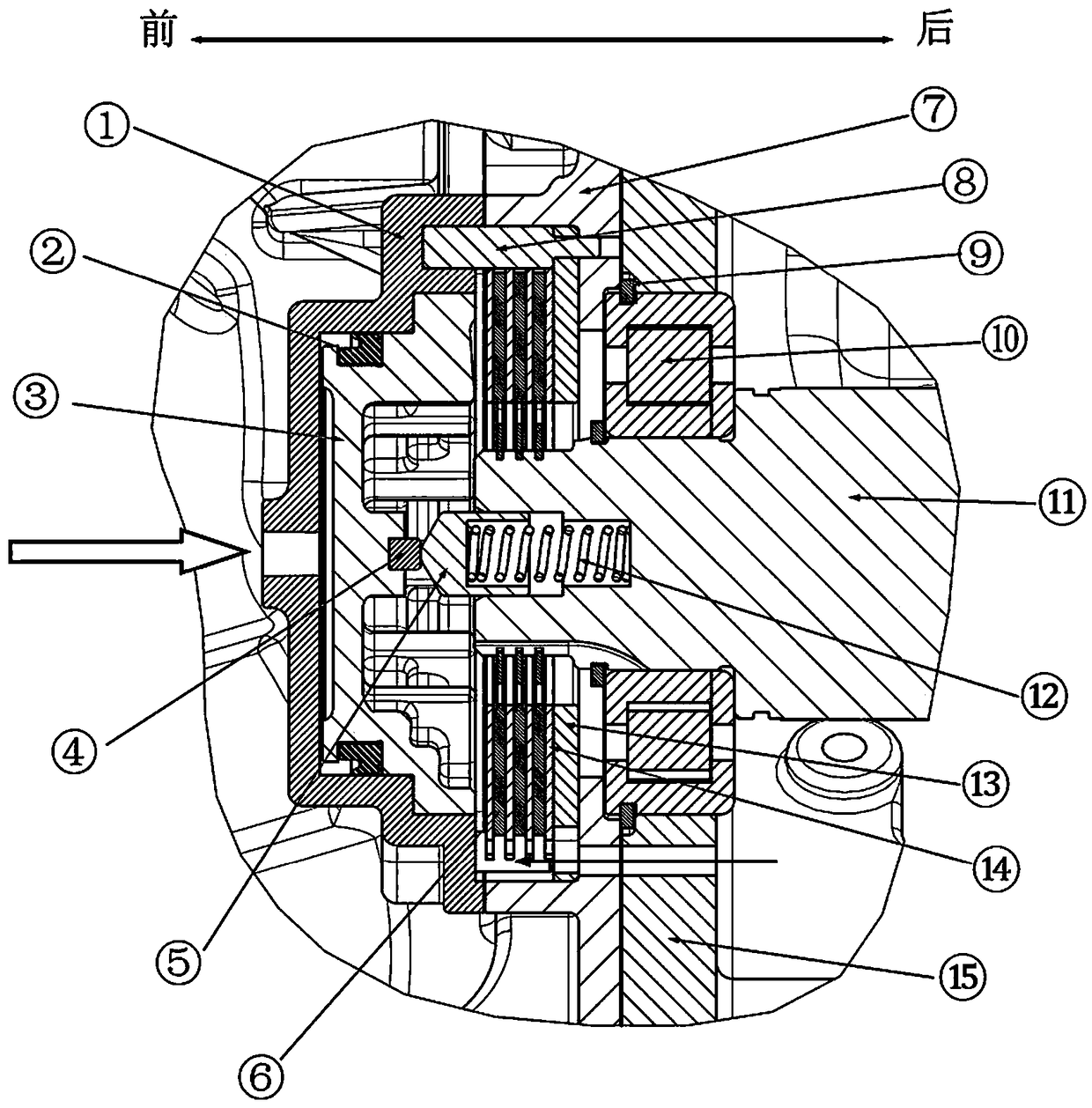
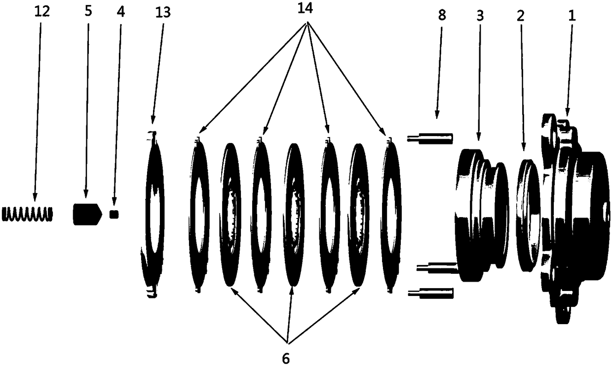
[0022] see Figure 1-2 The AMT intermediate shaft brake structure of the present invention includes an intermediate shaft 11 extending from the transmission housing 15 to the front end cover 1 of the clutch housing. A plurality of friction discs 6 rotating with the shaft are arranged at intervals on the outer circumference of the extension part of the intermediate shaft 11. The intermediate shaft The extension part of 11 is connected with the friction disc 6 through involute splines matched inside and outside. A brake disc 14 that does not rotate with the shaft is arranged between the friction discs 6, a piston 3 is arranged inside the front end cover 1 of the clutch housing, and a brake air inlet is opened on the front end cover 1 of the clutch housing, and the piston 3 and the front end of the clutch housing The inner walls of the cover 1 are sealed by a K...


PUM


Abstract

The invention relates to an AMT intermediate shaft braking structure. The AMT intermediate shaft braking structure comprises an intermediate shaft extending from a transmission housing to a front endcover of a clutch housing. A plurality of friction discs rotating along with the shaft are arranged at intervals on the outer periphery of the extension portion of the intermediate shaft. Braking discs which do not rotate along with the shaft are arranged between the friction discs. A piston is hermetically arranged in the front end cover of the clutch housing, and the front end cover of the clutch housing is internally provided with a braking airflow inlet. The center of the piston is connected with the axial center of the intermediate shaft through a compression spring. Under the action of air pressure, the piston overcomes the elasticity of the compression spring and pushes one ends of the braking discs to be combined with the friction discs, the rotating speed of the intermediate shaftis reduced by the torque generated by the friction between the braking discs and the friction discs, collected rotating speed signals are fed back to a transmission control unit by an intermediate shaft rotating speed sensor, and the braking of the intermediate shaft is released and gear shifting is carried out when the rotating speed of the intermediate shaft reaches a target rotating speed range. The internal space of the transmission housing is fully utilized. The AMT intermediate shaft braking structure has the advantages of being low in weight and little affected by external factors.

Description

technical field [0001] The invention relates to the field of gearbox processing and design, in particular to an AMT intermediate shaft braking structure. Background technique [0002] The Automatic Mechanical Transmission (AMT) is based on the traditional manual transmission, through the electronic control unit to realize the separation and combination of the clutch and the selection and shifting operations. [0003] When shifting gears in AMT, the two shafts in the main box need to be synchronized with the speed of the intermediate shaft, and in the process of upshifting, the two shafts need to be braked in order to make the speed of the intermediate shaft reach the target speed in the shortest time and complete the speed synchronization and shift gears. There are generally two types of structures currently used in AMT transmission brakes (Transmission Brake, TB for short). One is to use a brake structure outside the gearbox housing, and the other is to use the intermediat...

Claims


Application Information

Patent Timeline
Patent Type & Authority Applications(China)
IPC IPC(8): F16D55/22F16D65/14F16D65/853F16D121/20
CPCF16D55/22F16D65/14F16D65/853F16D2121/20
Inventor 李少林韩晓宇杨小辉
Owner SHAANXI FAST GEAR CO
Why Eureka
Try Eureka