Ventilation shoe

A ventilation device and air intake channel technology, which is applied to boot legs, shoe uppers, clothing, etc., can solve the problems of complex structure and overweight of the check valve, and achieve the effects of small touch, easy manufacture, and stable performance

Active Publication Date: 2018-12-21
INFOM
View PDF13 Cites 0 Cited by
  • Summary
  • Abstract
  • Description
  • Claims
  • Application Information

AI Technical Summary

Problems solved by technology

Therefore, the structure of the check valve is complex and heavy

Method used


Image

  • Ventilation shoe
  • Ventilation shoe
  • Ventilation shoe

Examples


no. 1 example

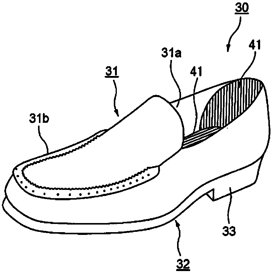
[0085] Such as figure 1 As shown, the ventilation boot 30 includes a vamp 31, a sole 32 and a ventilation device for ventilation inside the shoe 34.

[0086] A heel 33 is provided on a heel portion of the sole 32 . The ventilating boot 30 also includes: an inner sole plate 35, which contacts the rear of the foot; a middle sole plate 36, which is placed below the inner sole plate 35 and arranged to be stacked with the inner sole plate 35; a lower sole plate 37, which is placed on the Below the middle sole plate 36 and arranged to be stacked with the middle sole plate 36; Outer sole plate 38, which is placed under the lower sole plate 37 and arranged to be stacked with the lower sole plate 37. The inner sole plate 35 to the outer sole plate 38 correspond to the sole plates forming the sole 32 according to the invention.

[0087] The shoe interior 34 of the ventilation boot 30 is surrounded by the upper 31 and the sole 32 , and is formed between the upper 31 and the inner sole ...


PUM

PropertyMeasurementUnit
thicknessaaaaaaaaaa

Abstract

The present invention enables downsizing of a ventilation shoe and enables sufficient ventilation of the interior of the shoe. The present invention has: an upper (31); a sole (32) obtained by stacking a plurality of sole sheets; and a ventilation device for taking air into a shoe interior (34) and discharging air outside the shoe interior (34). The ventilation device is provided with: an air intake passage (L1) for taking in air; an air discharge passage (L2) for discharging air; and a pump chamber (P) for feeding the air taken in through the air intake passage (L1) to the air discharge passage (L2). The sole (32) is configured from a plurality of sole sheets being stacked on one another, and the pump chamber (P) is formed in a flattened shape between the sole sheets, and valve installation holes (152, 157) are formed in an intermediate sole sheet that is sandwiched between other sole sheets from above and below, and check valves (V1, V2) are respectively provided in said valve installation holes (152, 157) in such a manner as to be integrated therewith via a support member.

Description

technical field [0001] The invention relates to a ventilation boot. Background technique [0002] Poor ventilation inside the shoe. Wearing shoes for a long time can cause stuffy feet and make the wearer uncomfortable, and may even lead to athlete's foot. Therefore, a ventilation boot is proposed that is configured to provide a pump chamber in the sole of the shoe, and the pump chamber is compressed by the weight of the wearer on the shoe during walking and the load change due to bending, so that the air is released to the toes and reaches the inside of the shoe. ventilation. [0003] In the proposed configuration, the pump chamber is located in the thick heel section. The opening of the air intake channel connected with the outside air is provided in the area corresponding to the wearer's heel, and the opening of the air discharge channel is provided in the area around the toe. The intake channel and the exhaust channel are respectively connected with the pump chamber t...

Claims


Application Information

Patent Timeline
Patent Type & Authority Applications(China)
IPC IPC(8): A43B7/08A43B13/20
CPCA43B7/08A43B7/088A43B13/203A43B23/0245A43B13/20A43B7/081A43B13/16B32B3/266B32B5/18B32B2437/02
Inventor 伊藤隆好
Owner INFOM
Why Eureka
Try Eureka