
Pull rope sensor housing

A technology for pulling rope sensors and shells, which is applied in the field of sensor shells, and can solve problems such as the influence of sensor components and measurement accuracy, and achieve the effects of improving stability and accuracy, ensuring positioning accuracy, ensuring airtightness, and corrosion resistance

Pending Publication Date: 2018-12-18
天津市友发德众钢管有限公司 +1
View PDF5 Cites 0 Cited by
  • Summary
  • Abstract
  • Description
  • Claims
  • Application Information

AI Technical Summary

Problems solved by technology

[0003] However, when in use, due to the expansion and contraction of the drawstring, the undesirable components in the surrounding environment will be brought into the sensor. For example, in a highly corrosive environment, such as a humid and acidic environment, the acidic water vapor in the air will adhere to the drawstring It enters into the sensor and affects the sensor components, thereby affecting its measurement accuracy

Method used


Image

  • Pull rope sensor housing
  • Pull rope sensor housing
  • Pull rope sensor housing

Examples


Embodiment Construction

[0019] It should be noted that, in the case of no conflict, the embodiments of the present invention and the features in the embodiments can be combined with each other.

[0020] In describing the present invention, it should be understood that the terms "center", "longitudinal", "transverse", "upper", "lower", "front", "rear", "left", "right", " The orientations or positional relationships indicated by "vertical", "horizontal", "top", "bottom", "inner" and "outer" are based on the orientations or positional relationships shown in the drawings, and are only for the convenience of describing the present invention and Simplified descriptions, rather than indicating or implying that the device or element referred to must have a particular orientation, be constructed and operate in a particular orientation, and thus should not be construed as limiting the invention. In addition, the terms "first", "second", etc. are used for descriptive purposes only, and should not be understood ...


PUM


Abstract

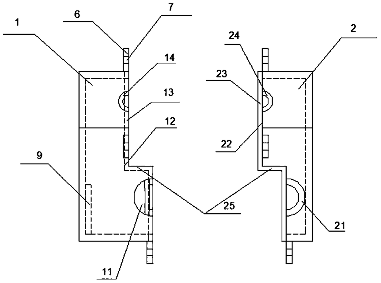
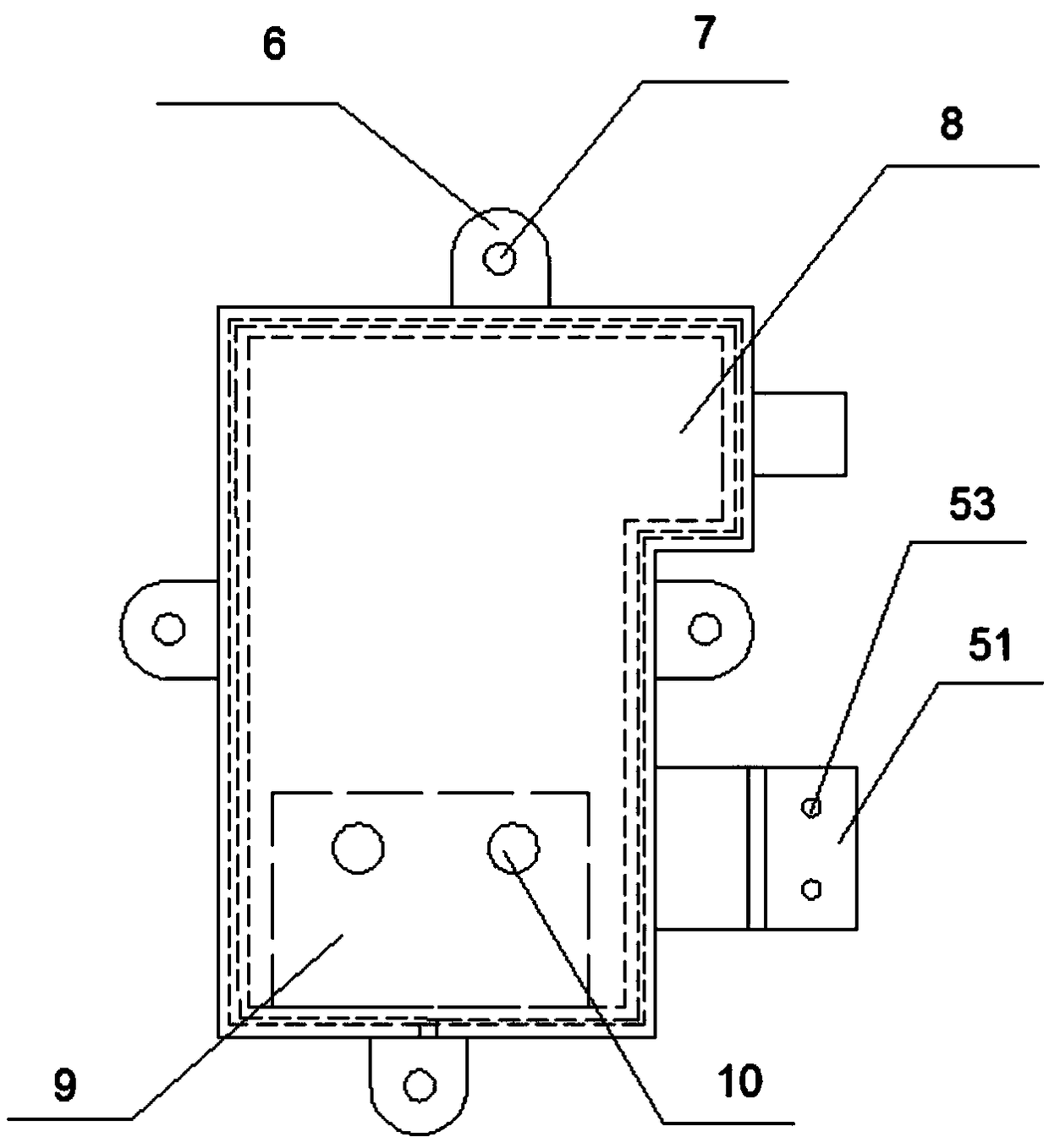
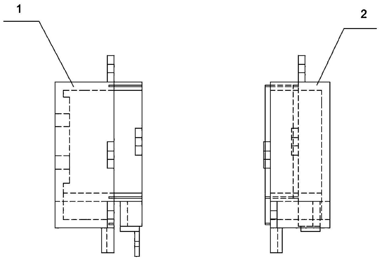
The invention discloses a pull rope sensor housing which comprises a first shell and a second shell. A first pull rope penetrating hole is formed on the first shell; a second pull rope penetrating hole is formed on the second shell; the first shell and the second shell are in detachable connection; the pull rope first penetrating hole and the second pull rope penetrating hole are connected into one integral pull rope penetrating hole; and a regulation extrusion mechanism is arranged on the end face of the pull rope penetrating hole and used for extruding a pull rope. According to the pull ropesensor housing provided by the invention, a fixed pressure plate and a movable pressure plate are arranged on the end face of the pull rope penetrating hole, a first elastic part and a second elasticpart are respectively arranged inside the pressure plates, the fixed pressure plate and the movable pressure plate form an adjustable flat nozzle extrusion type structure; the pull rope penetrates between two elastic parts; the first elastic part and the second elastic part are extruded by the movable pressure plate so as to filter out moisture and acid liquid on the pull rope; sealing performance and corrosion resistance of the housing are well ensured; and stability and accuracy of a sensor are improved.

Description

technical field [0001] The invention relates to the technical field of sensor casings, in particular to a pull cord sensor casing. Background technique [0002] Pull rope sensors are also called pull rope displacement sensors, pull rope electronic scales, and pull rope encoders. The pull rope sensors are wound by a stretchable stainless steel rope on a threaded hub, which is connected with a precision rotation sensor. , the sensor can be an incremental encoder, an absolute (independent) encoder, a hybrid or conductive plastic rotary potentiometer, a synchronizer or a resolver. In operation, the pull cord sensor is installed in a fixed position and the draw cord is attached to a moving object. The linear motion of the pull rope is aligned with the motion axis of the moving object. As movement occurs, the drawstring expands and contracts. [0003] However, when in use, due to the expansion and contraction of the drawstring, the undesirable components in the surrounding envi...

Claims


Application Information

Patent Timeline
Patent Type & Authority Applications(China)
IPC IPC(8): G01B21/02
CPCG01B21/02
Inventor 李茂津高强李相东陈自林李大华王亚林李栋何天林辛世龙薛涛王昭阳高洪泉沈洪宇陈自永刘坤鹏
Owner 天津市友发德众钢管有限公司
Learn More