Novel coal gasification process burner jet nozzle
A process burner and coal gasification technology, which is applied in the field of coal gasification to achieve the effects of increasing the contact area, reducing the surface area and improving the service life
- Summary
- Abstract
- Description
- Claims
- Application Information
AI Technical Summary
Problems solved by technology
Method used
Image
Examples
Embodiment 1
[0023] A preferred embodiment of the present invention will be described in detail below in conjunction with the accompanying drawings.
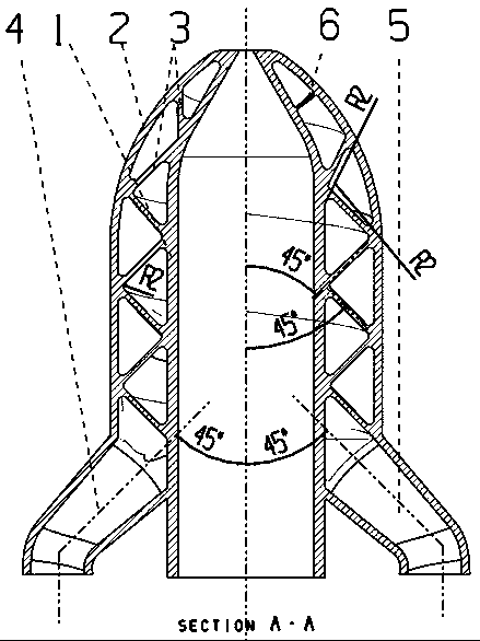
[0024] Such as figure 1 As shown, the coal gasification process burner nozzle of the present invention includes: nozzle inner wall 1 , nozzle outer wall (also called shell) 2 , runner partition 3 , water outlet 4 , water inlet 5 , and spoiler 6 . figure 2 Shown is a schematic diagram of the space structure of the flow channel separator of the present invention. Depend on figure 2 It can be seen that the flow channel partitions are in the shape of a helix, and adjacent partitions are perpendicular to each other.
[0025] Depend on figure 1 It can be seen that the nozzle at the front end of the nozzle of the present invention is ellipsoidal; the second half connected to the water outlet 4 and the water inlet 5 is cylindrical. The flow channel partition 3 forms an angle of 45° with the axis. In the cylindrical part, the adjacent flow cha...
Embodiment 2
[0034] A preferred embodiment of the present invention will be described in detail below in conjunction with the accompanying drawings.
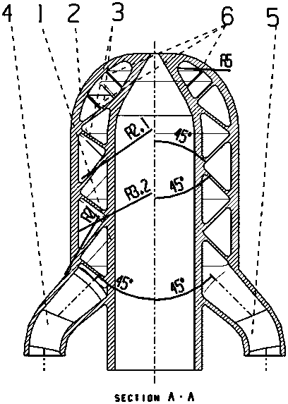
[0035] Such as image 3 As shown, the coal gasification process burner nozzle of the present invention includes: nozzle inner wall 1 , nozzle outer wall (also called shell) 2 , runner partition 3 , water outlet 4 , water inlet 5 , and spoiler 6 . image 3 Shown is a schematic diagram of the space structure of the flow channel separator of the present invention. Depend on Figure 4 It can be seen that there are six layers of runner partitions in total, with a rotating ladder structure, and adjacent partitions are perpendicular to each other.
[0036] Depend on figure 1 It can be seen that the nozzle part of the front end of the nozzle of the present invention is spherical, and the second half connected to the water outlet 4 and the water inlet 5 is cylindrical. The flow channel partition 3 forms an angle of 45° with the axis. In the cyli...
Embodiment 3
[0045] A preferred embodiment of the present invention will be described in detail below in conjunction with the accompanying drawings.
[0046] Such as figure 1 As shown, the coal gasification process burner nozzle of the present invention includes: nozzle inner wall 1 , nozzle outer wall (also called shell) 2 , runner partition 3 , water outlet 4 , water inlet 5 , and spoiler 6 . figure 2 Shown is a schematic diagram of the space structure of the flow channel separator of the present invention. Depend on figure 2 It can be seen that the flow channel partitions are in the shape of a helix, and adjacent partitions are perpendicular to each other.
[0047] Depend on figure 1 It can be seen that the nozzle at the front end of the nozzle of the present invention is in the shape of an ellipsoid, and the second half connected to the water outlet 4 and the water inlet 5 is in the shape of a cylinder. The flow channel partition 3 forms an angle of 45° with the axis. In the cyl...
PUM
| Property | Measurement | Unit |
|---|---|---|
| radius | aaaaa | aaaaa |
Abstract
Description
Claims
Application Information
 - R&D
- Intellectual Property
- Life Sciences
- Materials
- Tech Scout
- Unparalleled Data Quality
- Higher Quality Content
- 60% Fewer Hallucinations
Browse by: Latest US Patents, China's latest patents, Technical Efficacy Thesaurus, Application Domain, Technology Topic, Popular Technical Reports.
© 2025 PatSnap. All rights reserved.Legal|Privacy policy|Modern Slavery Act Transparency Statement|Sitemap|About US| Contact US: help@patsnap.com


