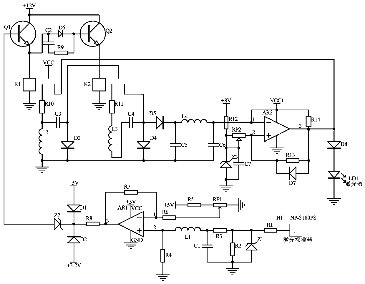
Bootstrap optical power control circuit of semiconductor laser pain therapy instrument
An optical power control, semiconductor technology, applied in the field of medical devices, can solve the problems of short treatment time, laser power attenuation, rise, etc., to achieve the effect of improving anti-interference ability, eliminating voltage changes, and constant optical power
- Summary
- Abstract
- Description
- Claims
- Application Information
AI Technical Summary
Problems solved by technology
Method used
Image
Examples
Embodiment 1
[0013] Embodiment 1, the bootstrap optical power control circuit of the semiconductor laser pain treatment instrument, the optical power signal acquisition circuit receives the laser power signal sent by the semiconductor laser pain treatment instrument laser LD1 through the laser detector of the model NP-3180PS, and the output is proportional to The 4-20mA current signal of the optical power of the laser is converted into a voltage signal by the current / voltage conversion circuit composed of resistor R1, voltage regulator Z1, and resistor R2. After that, the voltage signal is obtained by the subtractor with the operational amplifier AR1 as the core and proportional to the voltage difference. Amplify, the clamping circuit composed of diode D1 and diode D2 clamps +3.2V~+5V, the voltage regulator tube outputs after voltage stabilization, and the voltage difference signal after clamping and voltage stabilization is the first-level triode in the bootstrap boost regulation circuit T...
Embodiment 2
[0014] Embodiment 2, on the basis of Embodiment 1, the optical power signal acquisition circuit receives the laser power signal sent by the laser LD1 of the semiconductor laser pain treatment instrument through the laser detector of the model NP-3180PS, and the output is proportional to the optical power of the laser. The 4-20mA current signal is converted into a voltage signal by the current / voltage conversion circuit composed of resistor R1, voltage regulator tube Z1, and resistor R2. After that, the voltage signal is limited by resistor R3, filtered by inductor L1 and capacitor C1, and then sent to the operational amplifier AR1 The non-inverting input of the operational amplifier AR1 is subtracted from the threshold voltage of the inverting input of the operational amplifier AR1 (the voltage signal corresponding to the normal optical power of the laser), and proportionally amplified (the magnification is determined by the feedback resistor R7 through adjustment), and finally ...
PUM
 Abstract
Description
Claims
Application Information
 - Generate Ideas
- Intellectual Property
- Life Sciences
- Materials
- Tech Scout
- Unparalleled Data Quality
- Higher Quality Content
- 60% Fewer Hallucinations
Browse by: Latest US Patents, China's latest patents, Technical Efficacy Thesaurus, Application Domain, Technology Topic, Popular Technical Reports.
© 2025 PatSnap. All rights reserved.Legal|Privacy policy|Modern Slavery Act Transparency Statement|Sitemap|About US| Contact US: help@patsnap.com


