
Grid-connected point voltage fluctuation suppression method and new energy power station

A voltage fluctuation and fluctuation suppression technology, applied in the direction of AC network voltage adjustment, reactive power compensation, etc., can solve problems such as inability to inject reactive power, reactive power and voltage shocks at grid connection points, and influence grid stability, etc. The effect of autonomy

Pending Publication Date: 2021-07-02
SUNGROW POWER SUPPLY CO LTD
View PDF0 Cites 1 Cited by
  • Summary
  • Abstract
  • Description
  • Claims
  • Application Information

AI Technical Summary

Problems solved by technology

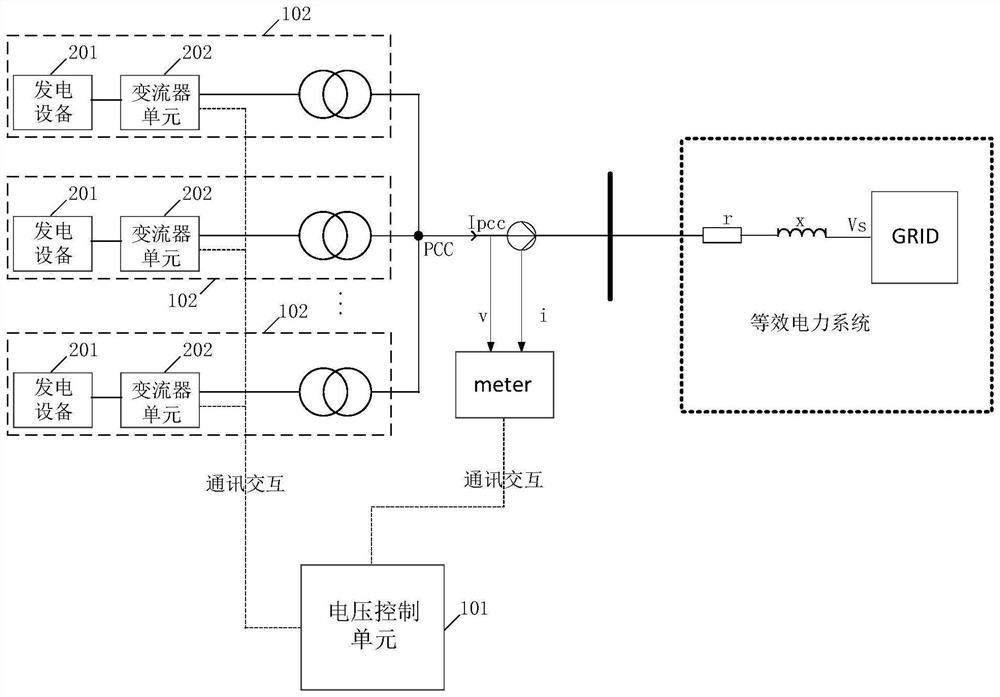
However, in practical applications, since the grid-connected point voltage is also affected by external voltage fluctuations, for example, changes from external loads or the impact of other nearby new energy power stations; it may cause the power station to inject too much reactive power Power, if there are multiple other new energy power stations nearby injecting a large amount of reactive power at the same time, it may cause the reactive power and voltage of the grid-connected point to fluctuate, thereby affecting the stability of the grid
[0004] Therefore, some national standards clearly state that new energy power stations need to be able to achieve regional autonomy for voltage fluctuations at grid-connected points, that is, each power station only needs to eliminate voltage changes caused by its own active power changes, and for voltage changes caused by external voltage fluctuations, Cannot inject reactive power
The current AVR cannot meet the requirement of regional autonomy, so a new solution is urgently needed to meet this requirement

Method used


Image

  • Grid-connected point voltage fluctuation suppression method and new energy power station
  • Grid-connected point voltage fluctuation suppression method and new energy power station
  • Grid-connected point voltage fluctuation suppression method and new energy power station

Examples


Embodiment Construction

[0038] The following will clearly and completely describe the technical solutions in the embodiments of the present invention with reference to the accompanying drawings in the embodiments of the present invention. Obviously, the described embodiments are only some, not all, embodiments of the present invention. Based on the embodiments of the present invention, all other embodiments obtained by persons of ordinary skill in the art without making creative efforts belong to the protection scope of the present invention.

[0039] In this application, the term "comprises", "comprises" or any other variation thereof is intended to cover a non-exclusive inclusion such that a process, method, article, or apparatus comprising a set of elements includes not only those elements, but also includes none. other elements specifically listed, or also include elements inherent in such a process, method, article, or apparatus. Without further limitations, an element defined by the phrase "com...


PUM


Abstract

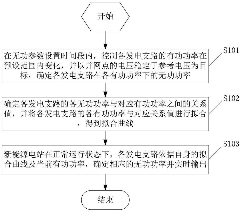
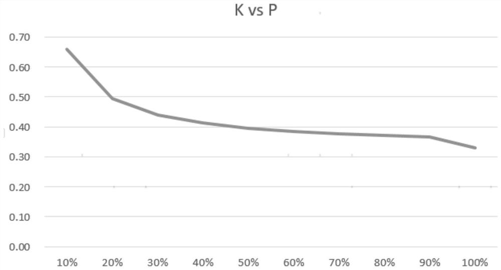
The invention provides a grid-connected point voltage fluctuation suppression method and a new energy power station, and the method comprises the steps: firstly, controlling the active power change of each power generation branch in a reactive parameter setting time period, and determining the reactive power of each power generation branch under each active power by taking the voltage of a grid-connected point to be stabilized at a reference voltage as a target; and determining a relation value between each reactive power of each power generation branch and the corresponding active power, and fitting the relation value with the corresponding active power to obtain a fitting curve. In a normal operation state, each power generation branch can determine corresponding reactive power and output the reactive power in real time according to a fitting curve of the power generation branch and the current active power, so that the voltage of a grid-connected point can be stabilized at the reference voltage; and moreover, the duration of the reactive power parameter setting time period is smaller than a preset value, so that the influence of external voltage fluctuation on the new energy power station can be ignored, and regional autonomy of grid-connected point voltage fluctuation is realized.

Description

technical field [0001] The invention relates to the technical field of grid-connected control, in particular to a method for suppressing voltage fluctuation at a grid-connected point and a new energy power station. Background technique [0002] With the rapid development of photovoltaic power generation, there are more and more application occasions for inverters, and the grid environment is becoming more and more complex, which puts forward new requirements for the adaptability of inverters. Moreover, as the penetration rate of new energy equipment is getting higher and higher, new energy power generation has a significant impact on power quality: both photovoltaic and wind energy have random characteristics, and changes in illumination or wind speed will lead to large fluctuations in the active power of grid-connected points. In the context of a power grid with a high penetration rate, the fluctuation of active power will cause fluctuations in the voltage at the grid-conne...

Claims


Application Information

Patent Timeline
Patent Type & Authority Applications(China)
IPC IPC(8): H02J3/16
CPCH02J3/16Y02E40/30
Inventor 潘年安赵天工
Owner SUNGROW POWER SUPPLY CO LTD
Learn More