Eureka AIR delivers breakthrough ideas for toughest innovation challenges, trusted by R&D personnel around the world.

Design method of synchronous motion transmission error curve and spiral bevel gear using transmission error curve

A transmission error and synchronous motion technology, which is applied in the field of spiral bevel gears, can solve the problems that the impact of changing teeth is not well resolved, and the superiority of the fourth-order transmission error curve cannot be fully utilized, so as to improve the load distribution between teeth , reduce vibration and shock, reduce the effect of shock and vibration

Active Publication Date: 2018-12-14
NORTHWESTERN POLYTECHNICAL UNIV
View PDF2 Cites 3 Cited by
  • Summary
  • Abstract
  • Description
  • Claims
  • Application Information

AI Technical Summary

Problems solved by technology

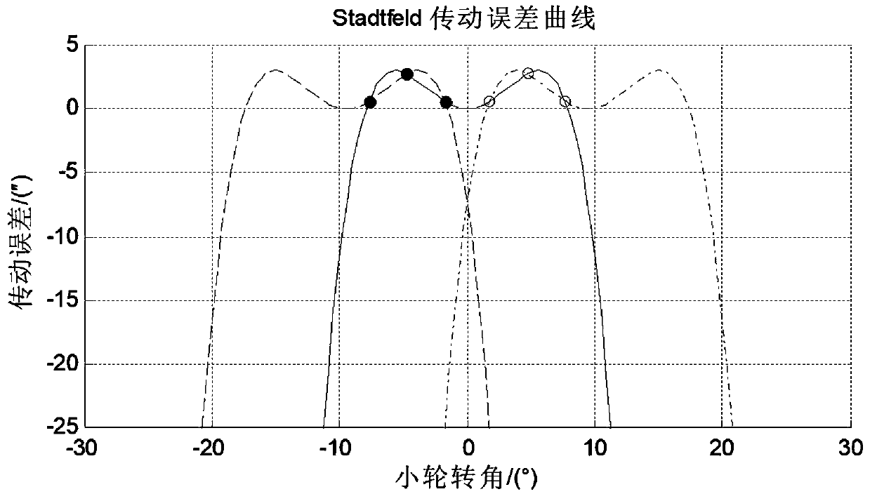
A closer look at the fourth-order transmission error curve of the Stadtfeld type also reveals that there is still a large relative speed step when changing gears, and the impact caused by the gear change has not been well resolved. The superiority of the fourth-order transmission error curve has not been fully utilized in the parameter design of Yue, which is contradictory and mutually restrictive.

Method used


Image

  • Design method of synchronous motion transmission error curve and spiral bevel gear using transmission error curve
  • Design method of synchronous motion transmission error curve and spiral bevel gear using transmission error curve
  • Design method of synchronous motion transmission error curve and spiral bevel gear using transmission error curve

Examples


Embodiment Construction

[0072] Embodiments of the present invention are described in detail below, and the embodiments are exemplary and intended to explain the present invention, but should not be construed as limiting the present invention.

[0073] (1) The formation principle of transmission error

[0074] The spiral bevel gear is a point contact local conjugate transmission, and the transmission error is defined as

[0075]

[0076] In the formula ——The actual rotation angle of driving wheel and driven wheel

[0077] ——The actual rotation angle of the driving wheel and the driven wheel when the reference point of the tooth surface meshes

[0078] z 1 ,z 2 ——The number of teeth of driving wheel and driven wheel

[0079] The first term in formula (1) is the rotation angle of the driven wheel when meshing relative to the reference point, is the rotation angle of the driving wheel when it is meshed relative to the reference point, is the theoretical rotation angle of the driven wheel...


PUM


Abstract

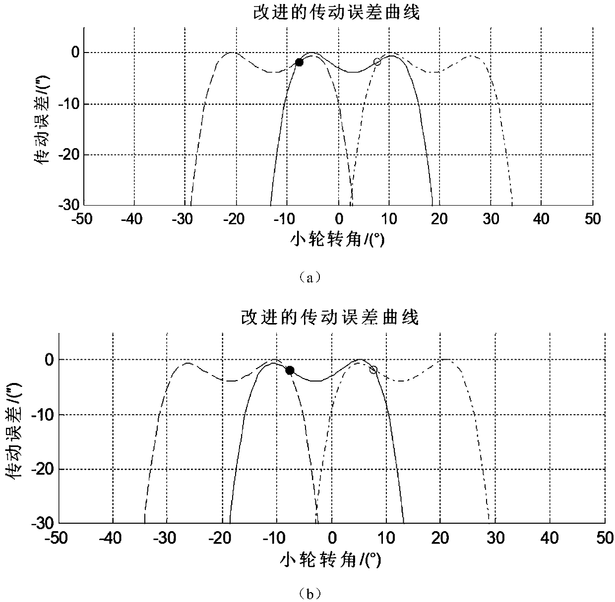
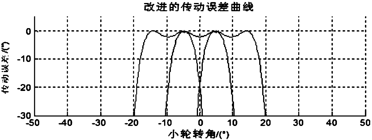
The invention provides a design method of a synchronous motion transmission error curve and a spiral bevel gear using the transmission error curve. The synchronous motion transmission error curve of the invention has two tooth changing points, which means that the number of tooth changing impact is small; the slope of adjacent transmission error curves is very close to each other at the point of gear change, which means that the angular velocity of gear change is almost the same. The engaging-in and engaging-out points are close to the inflection point of the transmission error curve, and thesecond derivative is zero, which means that the inertial dynamic load is almost zero when the gear is changed. The synchronous motion of the adjacent transmission error curve between the engaging-in and engaging-out points means that the non-uniform coefficient of load distribution between teeth is minimized. The above characteristics will greatly reduce the load on the teeth and vibration and impact caused by gear change, improve the load distribution between the teeth, and further improve the transmission performance of spiral bevel gears.

Description

technical field [0001] The invention relates to the technical field of gear transmission, in particular to a design method of a synchronous motion transmission error curve and a spiral bevel gear applying the transmission error curve. Background technique [0002] Spiral bevel gears are very important transmission parts in mechanical transmission, and are widely used in aircraft, ships and other precision machinery. The transmission performance of the spiral bevel gear is related to the transmission error curve and the contact impression of the tooth surface, and the transmission error curve has a greater impact on its vibration and noise. From a kinematic point of view, the gear transmission error is the difference between the actual rotation angle and the nominal rotation angle of the driven wheel, which is a function of the driving wheel rotation angle or time, and its slope indicates the relative speed change in the gear transmission. From a dynamic point of view, vibra...

Claims


Application Information

Patent Timeline
Patent Type & Authority Applications(China)
IPC IPC(8): G06F17/50F16H55/08
CPCF16H55/08G06F30/17G06F30/20G06F2111/10
Inventor 刘光磊刘明晨杨韬
Owner NORTHWESTERN POLYTECHNICAL UNIV
Why Eureka
Eureka Blog
Learn More