Tubular belt conveyor middle driving structure and tubular belt conveyor

A driving structure, the technology of the pipe belt conveyor, applied in the direction of the conveyor, the conveyor object, the conveyor control device, etc., can solve the problem that the long-distance transportation of materials cannot be satisfied, the strength of the tape is difficult to meet the long-distance transportation, and the strength of the tape is limited, etc. problem, to achieve the effect of good driving effect, compact driving structure and large conveying distance

Pending Publication Date: 2018-12-14
HUADIAN HEAVY IND CO LTD
View PDF0 Cites 0 Cited by
  • Summary
  • Abstract
  • Description
  • Claims
  • Application Information

AI Technical Summary

Problems solved by technology

[0004] In order to solve the technical problem that the tape strength of the existing pipe belt machine is difficult to meet the long-distance transportation, the invention provides a driving structure in the middle of the pipe belt machine
[0005] At the same time, in order to solve the technical problem that the existing pipe belt machine cannot meet the long-distance transportation of materials due to the limited strength of the tape, the present invention provides a tubular belt conveyor that breaks through the limitations of the existing technology and realizes the ultra-long-distance transportation of the pipe belt machine. machine

Method used


Image

  • Tubular belt conveyor middle driving structure and tubular belt conveyor
  • Tubular belt conveyor middle driving structure and tubular belt conveyor

Examples


Embodiment Construction

[0039] The technical solutions of the present invention will be clearly and completely described below in conjunction with the accompanying drawings. Apparently, the described embodiments are some of the embodiments of the present invention, but not all of them. Based on the embodiments of the present invention, all other embodiments obtained by persons of ordinary skill in the art without making creative efforts belong to the protection scope of the present invention.

[0040] In the description of the present invention, it should be noted that the terms "center", "upper", "lower", "left", "right", "vertical", "horizontal", "inner", "outer" etc. The indicated orientation or positional relationship is based on the orientation or positional relationship shown in the drawings, and is only for the convenience of describing the present invention and simplifying the description, rather than indicating or implying that the referred device or element must have a specific orientation, ...


PUM


Abstract

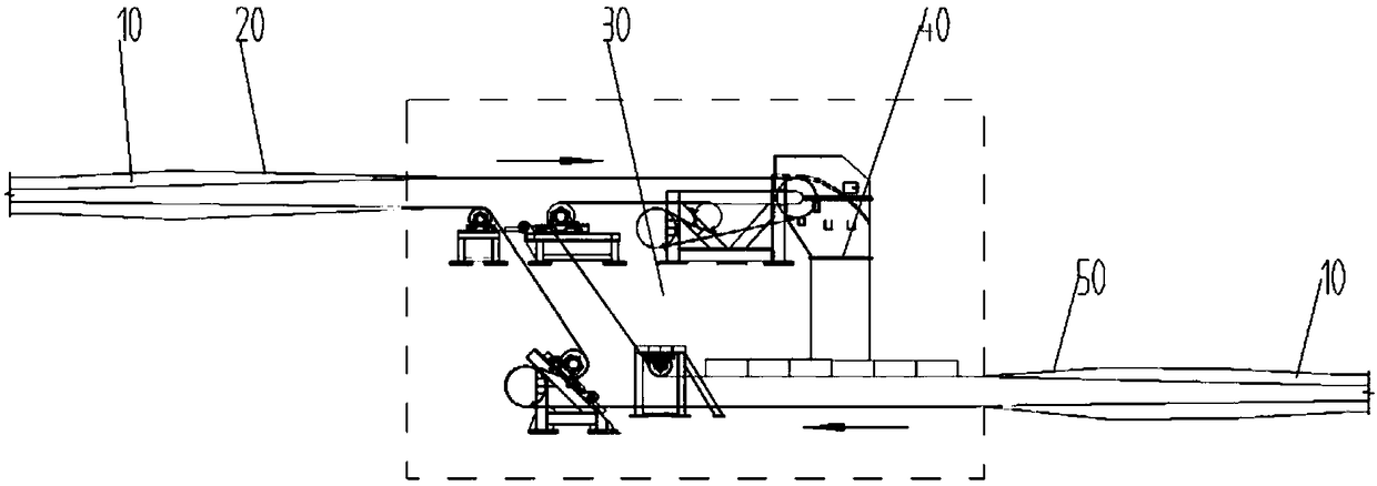
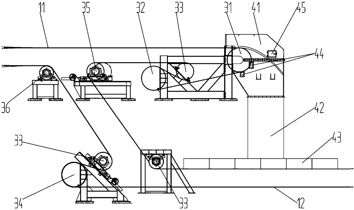
The invention relates to the technical field of material conveying, and particularly provides a tubular belt conveyor middle driving structure and a tubular belt conveyor. The tubular belt conveyor middle driving structure is arranged at a tubular section of the tubular belt conveyor and comprises a transition unfolding mechanism, a middle driving mechanism, a material transferring mechanism and atransition tube forming mechanism which are sequentially arranged; the transition unfolding mechanism is connected with the tubular section and used for unfolding an adhesive tape of the tubular section; the middle driving mechanism is installed behind the transition unfolding mechanism and used for driving the unfolded adhesive tape; a feeding opening of the material transferring mechanism is connected to the adhesive tape position in front of the middle driving mechanism, and a discharging opening of the material transferring mechanism is connected to the position above the adhesive tape behind the middle driving mechanism; and the transition tube forming mechanism is connected with the tubular section of the tubular belt conveyor and used for forming the unfolded adhesive tape to be intube shape. According to the tubular belt conveyor middle driving structure and the tubular belt conveyor, the driving structure is arranged so that the tubular belt conveyor breaks through existingconveying distance limitation, material extra-long distance conveying is achieved, the tubular belt conveyor does not need to be shut down in the conveying process, the material transferring links arereduced, and the problems about material blockage and tape stacking are solved.

Description

technical field [0001] The invention relates to the technical field of material conveying, in particular to a driving structure in the middle of a tubular belt conveyor and a tubular belt conveyor. Background technique [0002] Pipe belt conveyor is an environmentally friendly conveying equipment that wraps materials in a conveyor belt. Due to its advantages of environmental protection, flexibility, and long-distance transportation, the pipe belt conveyor has been widely used in the world. [0003] In the long-distance transportation, the belt conveyor is limited by the strength of the belt and the driving arrangement, and the transportation distance is limited. At present, it is difficult for a single belt conveyor at home and abroad to exceed 10km. With the development of pipe machine technology and the impact of environmental protection policies, the demand for long-distance pipe machine transportation is getting higher and higher. With the increase of transportation dist...

Claims


Application Information

Patent Timeline
Patent Type & Authority Applications(China)
IPC IPC(8): B65G15/08B65G23/04B65G45/10B65G43/00
CPCB65G15/08B65G23/04B65G43/00B65G45/10B65G2203/042
Inventor 崔志远张伟恒
Owner HUADIAN HEAVY IND CO LTD
Why Eureka
Try Eureka