A miniaturized microstrip line structure multi-branch loading dispersive delay line

A technology of microstrip line and delay line, which is applied in the field of miniaturized microstrip line structure multi-twig loading dispersion delay line, can solve the problems of unsuitable millimeter wave and terahertz frequency, etc., and achieve simple structure, broad application prospect and good performance Effect

Active Publication Date: 2018-12-11
FUZHOU UNIV
View PDF4 Cites 3 Cited by
  • Summary
  • Abstract
  • Description
  • Claims
  • Application Information

AI Technical Summary

Problems solved by technology

SAW devices are widely used in the microwave industry, but due to material limitations, their frequencies are mostly below the X-band, and are not suitable for millimeter-wave and terahertz frequencies

Method used


Image

  • A miniaturized microstrip line structure multi-branch loading dispersive delay line
  • A miniaturized microstrip line structure multi-branch loading dispersive delay line
  • A miniaturized microstrip line structure multi-branch loading dispersive delay line

Examples


Embodiment Construction

[0032] The present invention will be further described below in conjunction with the accompanying drawings and embodiments.

[0033] It should be pointed out that the following detailed description is exemplary and intended to provide further explanation to the present application. Unless defined otherwise, all technical and scientific terms used herein have the same meaning as commonly understood by one of ordinary skill in the art to which this application belongs.

[0034] It should be noted that the terminology used here is only for describing specific implementations, and is not intended to limit the exemplary implementations according to the present application. As used herein, unless the context clearly dictates otherwise, the singular is intended to include the plural, and it should also be understood that when the terms "comprising" and / or "comprising" are used in this specification, they mean There are features, steps, operations, means, components and / or combinatio...


PUM


Abstract

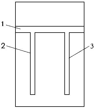
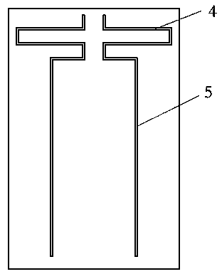
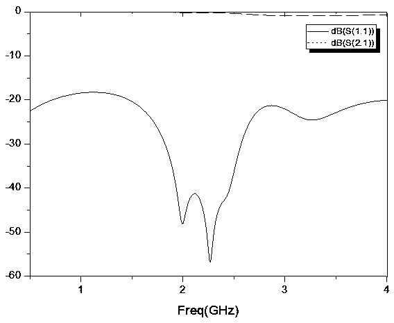
The invention relates to amulti-branch loading dispersive delay line with miniaturized microstrip line structure. The multi-branch loading dispersive delay line includes a conductor ground plane on one side of a dielectric substrate, a main transmission microstrip line on the other side of the dielectric substrate and a multi-branch loading stub on the same side of the microstrip line. The multi-branch loading delay line comprises a conductor ground plane on one side of the dielectric substrate, a main transmission microstrip line on the other side of the dielectric substrate and a stub on thesame side of the microstrip line. The ground plane includes a number of groove lines corresponding to the loading stub, the position of the groove lines corresponding to the position of the stub. Asthat groove line on the floor isbent and the stub line is positioned on one side of the main transmission microstrip line, the miniaturization of the dispersive delay line of the invention is realize.By loading stubs of the same size, the delay time increases linearly with the number of stubs loaded. The invention has the advantages of small size, simple structure and good performance, and has good delay characteristics in a specific frequency range.

Description

technical field [0001] The invention relates to the field of delay line design, in particular to a miniaturized microstrip line structure multi-twig loaded dispersion delay line. Background technique [0002] A delay line is an element or device used to delay an electrical signal for a period of time. The delay line should have a flat amplitude-frequency characteristic and a certain phase shift characteristic (or delay frequency characteristic) in the passband, and it must have an appropriate matching impedance and a small attenuation. Group delay engineering is widely used in phased array elements, analog signal processing, and group delay equalization. Commonly used delay lines are magnetostatic wave (MSW) dispersive delay line and surface acoustic wave (SAW) dispersive delay line. [0003] Magnetostatic wave (MSW) dispersive delay lines, exploiting the intrinsic dispersive film in the ferrimagnetic quasi-static mode, can be controlled via layer, stripline, and boundary ...

Claims


Application Information

Patent Timeline
Patent Type & Authority Applications(China)
IPC IPC(8): H01P9/00
CPCH01P9/00Y02D30/70
Inventor 袁家德李玉洁吴石基苏凯雄
Owner FUZHOU UNIV
Why Eureka
Try Eureka