Lenses, lens antennas and electronic equipment

A technology of lens antenna and electronic equipment, applied in the field of lens, lens antenna and electronic equipment, can solve the problems of unfavorable electronic equipment integration, large lens section, limited scanning angle of lens antenna, etc.

Active Publication Date: 2021-05-11
GUANGDONG OPPO MOBILE TELECOMM CORP LTD
View PDF4 Cites 0 Cited by
  • Summary
  • Abstract
  • Description
  • Claims
  • Application Information

AI Technical Summary

Problems solved by technology

[0003] In order to solve the problem that the scanning angle of the lens antenna is limited, and the lens has a large cross-section that is not conducive to integration in electronic equipment, the embodiment of the present application provides a lens, a lens antenna including the lens, and a lens antenna including the lens antenna. Electronic equipment

Method used


Image

  • Lenses, lens antennas and electronic equipment
  • Lenses, lens antennas and electronic equipment
  • Lenses, lens antennas and electronic equipment

Examples


Embodiment Construction

[0035] In order to facilitate the understanding of the present application, the present application will be described more fully below with reference to the relevant drawings. Preferred embodiments of the application are shown in the accompanying drawings. However, the present application can be embodied in many different forms and is not limited to the embodiments described herein. On the contrary, the purpose of providing these embodiments is to make the understanding of the disclosure of the application more thorough and comprehensive.

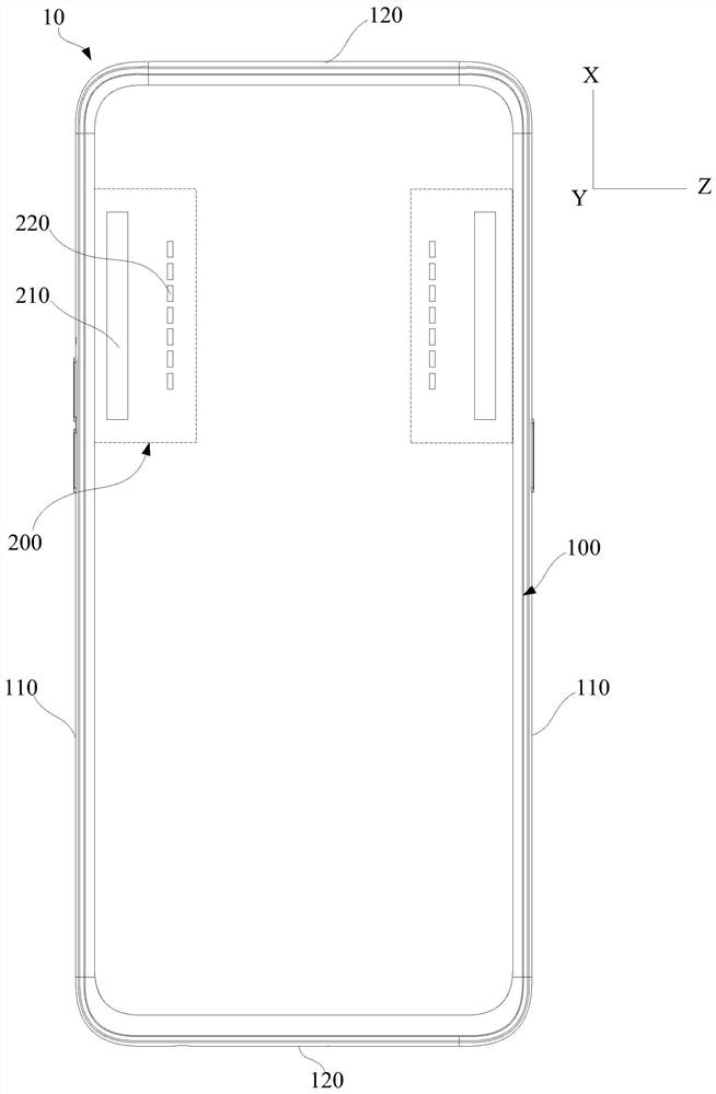
[0036] refer to figure 1 As shown, this application will take a smart phone as an example to describe the electronic device 10 . Those skilled in the art can easily understand that the electronic device 10 of the present application can be any device with communication and storage functions, such as smart phones, tablet computers, notebook computers, portable phones, video phones, digital still cameras, e-book readers, Smart terminals su...


PUM


Abstract

The application relates to a lens, a lens antenna and an electronic device. The lens includes a substrate layer and a conductive layer; the conductive layer is attached to the substrate layer, the conductive layer is attached to the substrate layer, and the conductive layer is provided with an array unit and a graphic unit , the array unit includes a plurality of hollow grooves, the plurality of hollow grooves are opened in the conductive layer and arranged at intervals along the first direction; the graphic unit is obtained by arraying the array unit toward both sides along the second direction, and the second direction is perpendicular to the first direction; Wherein, each hollow groove is provided with a conductive sheet, and the conductive sheet is provided with a crease line slit, the fold line slit includes a first slit and a second slit, the end of the first slit communicates with the end of the second slit and forms an included angle, and The angle formed by the first slit and the second slit has a gradual change in the first direction. In the present application, the phase delay is realized by controlling the opening angle of the first slot and the second slot, so that the electromagnetic waves radiated by the feed source far away from the focal point can be better converged, and the scanning angle of the lens antenna is greatly improved.

Description

technical field [0001] The present application relates to the field of microwave communication, in particular to a lens, a lens antenna and electronic equipment. Background technique [0002] Dielectric lens antennas are a common form of implementing beam scanning or multiple beams. In the lens antenna of the related art, the electromagnetic waves radiated by the feed far away from the focus of the lens cannot be well converged, so that the scanning angle of the lens antenna is limited, and the lens has a large cross-section, which is not conducive to integration in electronic devices. Contents of the invention [0003] In order to solve the problem that the scanning angle of the lens antenna is limited, and the lens has a large cross-section that is not conducive to integration in electronic equipment, the embodiment of the present application provides a lens, a lens antenna including the lens, and a lens antenna including the lens antenna. Electronic equipment. [0004...

Claims


Application Information

Patent Timeline
Patent Type & Authority Patents(China)
IPC IPC(8): H01Q15/02H01Q19/06H01Q1/50H01Q1/22H01Q21/00
CPCH01Q1/22H01Q1/50H01Q15/02H01Q19/06H01Q21/0006
Inventor 杨帆
Owner GUANGDONG OPPO MOBILE TELECOMM CORP LTD
Why Eureka
Try Eureka