
A rail profile detection method and system based on EPNP

A detection system and rail technology, applied in the field of image processing, can solve problems such as low precision and long time consumption

Pending Publication Date: 2018-12-11
WUHAN UNIV OF TECH
View PDF2 Cites 15 Cited by
  • Summary
  • Abstract
  • Description
  • Claims
  • Application Information

AI Technical Summary

Problems solved by technology

This method has strict requirements on the relative positions of the camera, laser and the measured rail, and it takes a long time and the accuracy is not high

Method used


Image

  • A rail profile detection method and system based on EPNP
  • A rail profile detection method and system based on EPNP
  • A rail profile detection method and system based on EPNP

Examples


Embodiment Construction

[0079] In order to make the object, technical solution and advantages of the present invention more clear, the present invention will be further described in detail below in conjunction with the examples. It should be understood that the specific embodiments described here are only used to explain the present invention, not to limit the present invention.

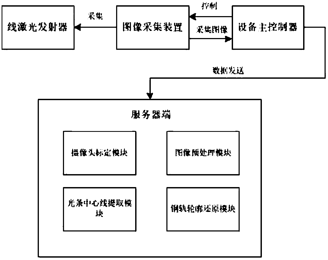
[0080] like figure 1 As shown, a rail profile detection system based on EPNP includes:

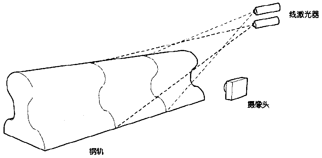
[0081] A line laser emitter is used to emit a laser line to the rail to be detected to form a laser light strip, and the laser light strip corresponds to the outer edge of the cross section of the rail;

[0082] The image acquisition device is used to collect the rail image with the laser light strip on the surface through the camera;

[0083] The main controller of the equipment is used to send the rail image data collected by the image acquisition device to the server;

[0084] The server side is used to receive the image data sent...


PUM


Abstract

The invention discloses a rail profile detection method and system based on EPNP. The system comprises: a line laser emitter, which is used for emitting laser lines to the rail to be detected to formlaser light strips, wherein the laser light strips correspond to the outer edge of the cross section of the rail; an image acquisition device for acquiring an image of a rail with a laser beam attached to a surface through a camera; a main controller of the equipment, which is used for sending the rail image data collected by the image collecting device to the server end.; and a server end, whichis used for receiving the image data sent by the main controller of the equipment, extracting the centerline of the light stripe in the image, obtaining the rail profile, and calculating the rail weardegree. The invention solves the problems of long time consumption and low precision of a conventional rail profile detection method, and has the advantages of low time complexity and high precision.

Description

technical field [0001] The invention relates to image processing technology, in particular to an EPNP-based rail profile detection method and system. Background technique [0002] In recent years, with the rapid development of my country's national economy, transportation has developed as a mobile carrier of the national economy, especially the development of high-speed railways. With the increase of the frequency of use of the rail, the wear of the rail is also increasing, and the service life is getting shorter and shorter. The excessive wear of the rail will pose a great threat to the safety of the train, so regular rail profile detection and maintenance work is necessary. [0003] At present, the known detection methods of rail profile include mechanical contact measurement and non-contact measurement. The mechanical contact measurement method can only qualitatively measure the geometric parameters of the rail profile, but cannot measure the rail in all directions. It ...

Claims


Application Information

Patent Timeline
IPC IPC(8): G06T7/00G06T7/11G06T7/136G06T7/62G06T7/80G01B11/25
CPCG01B11/2513G06T7/0004G06T2207/10004G06T2207/30164G06T7/11G06T7/136G06T7/62G06T7/80
Inventor 尹勇王阳刘宇峰齐雨航夏雨李文虎
Owner WUHAN UNIV OF TECH
Learn More