Eureka AIR delivers breakthrough ideas for toughest innovation challenges, trusted by R&D personnel around the world.

Digital image feeler vector coordinate transform calibration and error correction method and its device

A technology of coordinate transformation and error correction, which is applied in the field of vector coordinate transformation calibration and error correction of digital image probes and its devices, to meet the requirements of high-precision measurement, improve the accuracy of the entire field of view, and prevent measurement errors

Inactive Publication Date: 2008-12-31
XI AN JIAOTONG UNIV
View PDF2 Cites 34 Cited by
  • Summary
  • Abstract
  • Description
  • Claims
  • Application Information

AI Technical Summary

Problems solved by technology

[0016] The purpose of the present invention is to provide a digital imaging probe vector coordinate transformation calibration and error correction method and its device that comprehensively consider multiple practical application factors, thereby solving the problem of accurate calibration and measurement of the digital imaging probe

Method used


Image

  • Digital image feeler vector coordinate transform calibration and error correction method and its device
  • Digital image feeler vector coordinate transform calibration and error correction method and its device
  • Digital image feeler vector coordinate transform calibration and error correction method and its device

Examples


Embodiment Construction

[0038] The present invention will be described in further detail below in conjunction with the accompanying drawings.

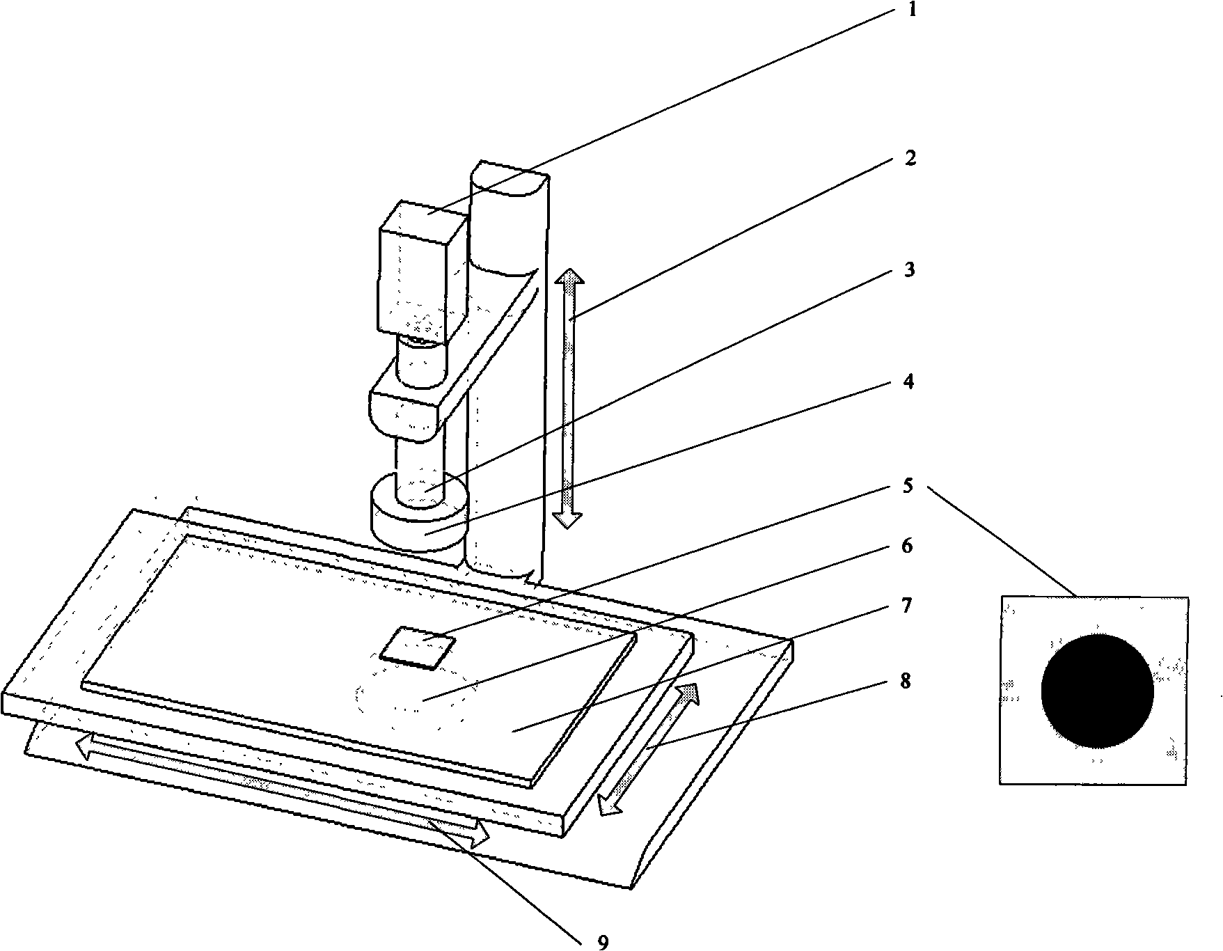
[0039] see image 3 , the device of the present invention includes the X-axis guide rail and the precision grating 9, the Y-axis guide rail and the precision grating 8, the Z-axis guide rail and the precision grating 2, the Z-axis guide rail and the precision grating 2 driven by the motor perpendicular to each other along the X, Y, and Z directions. The grating 2 is sequentially installed with an area array CCD1, a continuous zoom optical lens 3 and a top ring light 4 from top to bottom. The entire axis, that is, the imaging optical axis, is perpendicular to the XOY plane, and a bottom is provided on the table formed by the X and Y axes Parallel contour light 6, glass bearing workbench 7 and calibration plate 5 of standard circle, said area array CCD1, optical lens 3, top ring light 4 and bottom parallel contour light 6 are coaxially installed.

[0040] The ...


PUM


Abstract

The invention discloses a method for the calibration of vectorial coordinate transformation and the modification of errors of a digital image probe, and a device thereof; the noncontact optical measurement principle is adopted to realize the precise calibration and accurate modification of errors of the image probe in high-accurate two-dimensional measurement and ensure an accurate measurement result. The method of calibration is realized completely on the basis of the measuring principle of the image probe, without the existence of the errors of calibration principle. The process of calibration is based on the self-calibration principle, a virtual calibration point is formed by fixing a target object and moving the probe, then the calibration operation is fulfilled by constructing a vector, therefore, the operability of equipment is improved; by calculating the position of the image optical centre of an probe image sensor to be taken as the calibration origin, a new measurement error caused by the offset of a coordinate system is avoided to be introduced after the multiplying power of the probe is adjusted, the requirements of measurement in different application situations are ensured, and as the probe self-calibration technology is adopted, the calibration of the probe is ensured to have very high accuracy; the error self-modification is realized by moving a precise three-dimensional moving mechanical device to extract error meshes.

Description

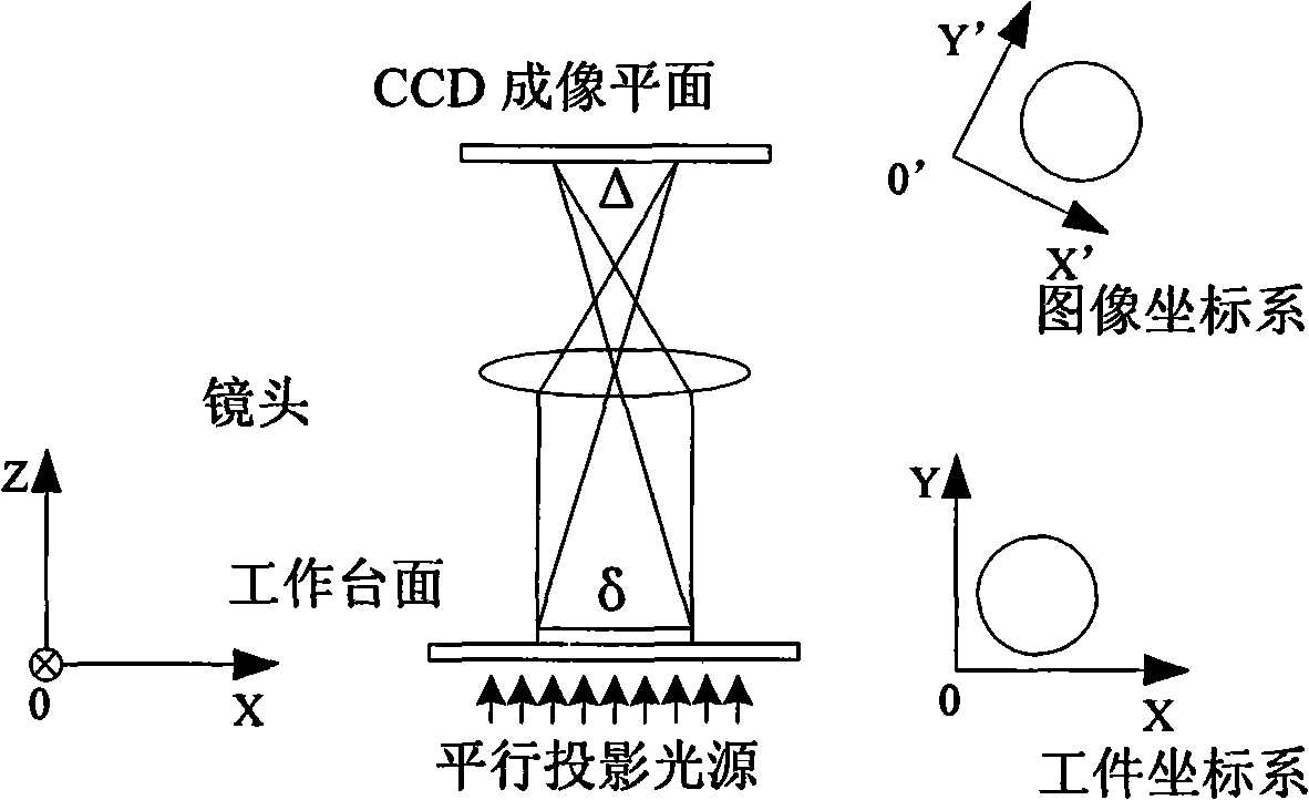
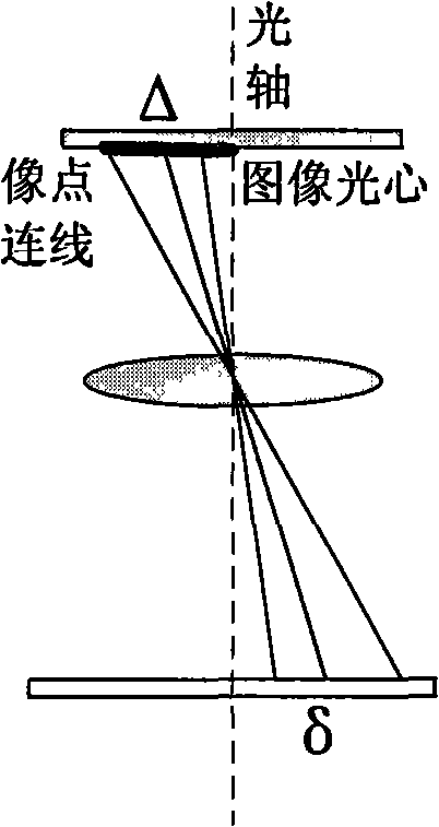
technical field [0001] The invention relates to a digital image measuring head vector coordinate transformation calibration and error correction method and device thereof. Background technique [0002] Digital image measurement can be widely used in actual production and life, and has very obvious measurement advantages for small and thin workpieces. Digital image measurement adopts the principle of optical triangulation, and reflects the displacement δ of the object point on the measured plane through the displacement Δ of the image point on the area array CCD photosensitive chip, so as to realize the measurement of the measured size in the lens focal plane. Digital image measurement technology has a very wide range of applications in precision measurement, microscopic size and structure detection, and other precision optical testing fields, and has very important application requirements and values. [0003] Its schematic diagram (only one section is given in the figure) ...

Claims


Application Information

Patent Timeline
Patent Type & Authority Applications(China)
IPC IPC(8): G01B11/00
Inventor 丁建军蒋庄德李兵郭俊杰张飞
Owner XI AN JIAOTONG UNIV
Why Eureka
Eureka Blog
Learn More