Supercharge Your Innovation With Domain-Expert AI Agents!

Burr polishing device for bending dies

A mold and burr technology, which is applied in the field of grinding machine grinding, can solve the problems of labor consumption and low efficiency, and achieve the effect of reducing labor force, improving efficiency and increasing the scope of use

Inactive Publication Date: 2018-12-11
马鞍山市国菱机械刃模有限公司
View PDF5 Cites 1 Cited by
  • Summary
  • Abstract
  • Description
  • Claims
  • Application Information

AI Technical Summary

Problems solved by technology

[0003] In view of the above-mentioned shortcomings of the prior art, the purpose of the present invention is to provide a bending mold burr grinding device, which is used to solve the problems of low efficiency and labor-intensive grinding process of existing trapezoidal bending molds during production

Method used


Image

  • Burr polishing device for bending dies
  • Burr polishing device for bending dies
  • Burr polishing device for bending dies

Examples


Embodiment 1

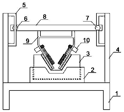
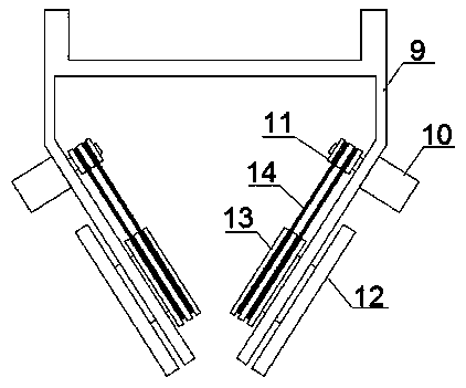
[0016] Such as Figure 1-3 As shown, the present invention discloses a bending mold burr grinding device, comprising: frame 1, fixture 2, mold 3, support plate 4, bracket 5, slide rail 6, ball screw module 7, slide plate 8, support Frame 9, DC motor 10, pulley one 11, grinding disc 12, pulley two 13, belt 14, described frame 1 is fixed with fixture 2 by bolts, mold 3 is clamped in described fixture 2, described The left and right ends of the upper plane of the frame 1 are respectively fixed with support plates 4 by bolts, and the relative positions of the opposite surfaces of the two support plates 4 are respectively fixed with brackets 5 by bolts. On the bracket at the left end of the frame 1 A slide rail 6 is fixed by bolts, and a ball screw module 7 is fixed by bolts on the bracket 5 at the right end of the frame 1, and a slide plate 8 is slidably installed on the slide rail 6, and the slide plate 8 and the ball The ball nuts of the lead screw module 7 are fixedly connecte...

Embodiment 2

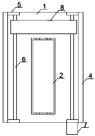
[0022] The structure of the bending mold burr grinding device in the first embodiment is basically the same as that in the first embodiment, the difference is that in this embodiment: by Figure 4 It can be seen that the groove of the mold 3 is in the shape of a cuboid, and the two legs of the support frame 9 are arranged vertically.

[0023] Therefore, as an optimization, the two legs of the support frame 9 in the present invention can be changed according to the shape of the groove on the mold 3, so as to complete the grinding.

[0024] The beneficial effects of the present invention: the ball screw module drives the slide plate to move on the slide rail, and the traditional manual movement is replaced by precise mechanical movement, which can improve the accuracy of grinding, improve the efficiency of grinding, and reduce the traditional manual grinding. Consuming labor; by making the two legs of the support frame parallel to the left and right inner walls of the groove of ...


PUM


Abstract

The invention discloses a burr polishing device for bending dies. The burr polishing device comprises a framework, a fixture, a die, support plates, brackets, slide rails, a ball screw module, a slideplate, a support frame, direct-current motors, first belt pulleys, abrasive discs, second belt pulleys and belts. The slide plate is slidably mounted on the slide rails and is fixedly connected withball nuts of the ball screw module, the support frame is fixed to a lower plane of the slide plate by the aid of bolts, the direct-current motors are fixed onto two leg plates of the support frame bythe aid of bolts, the abrasive discs are rotationally mounted on the support frame via bearings, the first belt pulleys are fixedly mounted on output shafts of the direct-current motors via bolts, thesecond belt pulleys are fixedly mounted on rotary shafts of the abrasion discs via bolts, and the first belt pulleys are connected with the second belt pulleys by the belts. The burr polishing devicehas the advantages that the burr polishing device is convenient to use, the polishing efficiency can be improved, the labor intensity of workers can be relieved, and the like.

Description

technical field [0001] The invention relates to a grinding device, in particular to the field of grinding machine grinding. Background technique [0002] In industrial production, some iron plates need to be bent into different shapes. Bending molds are needed in the bending process. Different bending molds can be bent into different shapes. Trapezoidal bending molds are one of them. There are trapezoidal grooves in the trapezoidal bending die. Due to the special shape of the trapezoidal grooves, it is very inconvenient to grind burrs. Contents of the invention [0003] In view of the above-mentioned shortcomings of the prior art, the purpose of the present invention is to provide a bending mold burr grinding device, which is used to solve the problems of low efficiency and labor-intensive grinding process of the existing trapezoidal bending mold during production. [0004] In order to achieve the above purpose and other related purposes, the present invention discloses a...

Claims


Application Information

Patent Timeline
IPC IPC(8): B24B19/20B24B41/06
CPCB24B19/20B24B41/06
Inventor 刘孝俊
Owner 马鞍山市国菱机械刃模有限公司
Features
  • R&D
  • Intellectual Property
  • Life Sciences
  • Materials
  • Tech Scout
  • Unparalleled Data Quality
  • Higher Quality Content
  • 60% Fewer Hallucinations
Learn More