Machining cutter
A machining and cutting tool technology, applied in the field of cutting tools, can solve the problems of weak bonding force between diamond coating and cemented carbide substrate, large difference in thermal expansion coefficient between coating and substrate, and no bonding force of diamond coating cutting tool, etc., to achieve The effect of low scrap rate, reduced inspection frequency and long service life
- Summary
- Abstract
- Description
- Claims
- Application Information
AI Technical Summary
Problems solved by technology
Method used
Image
Examples
Embodiment 1
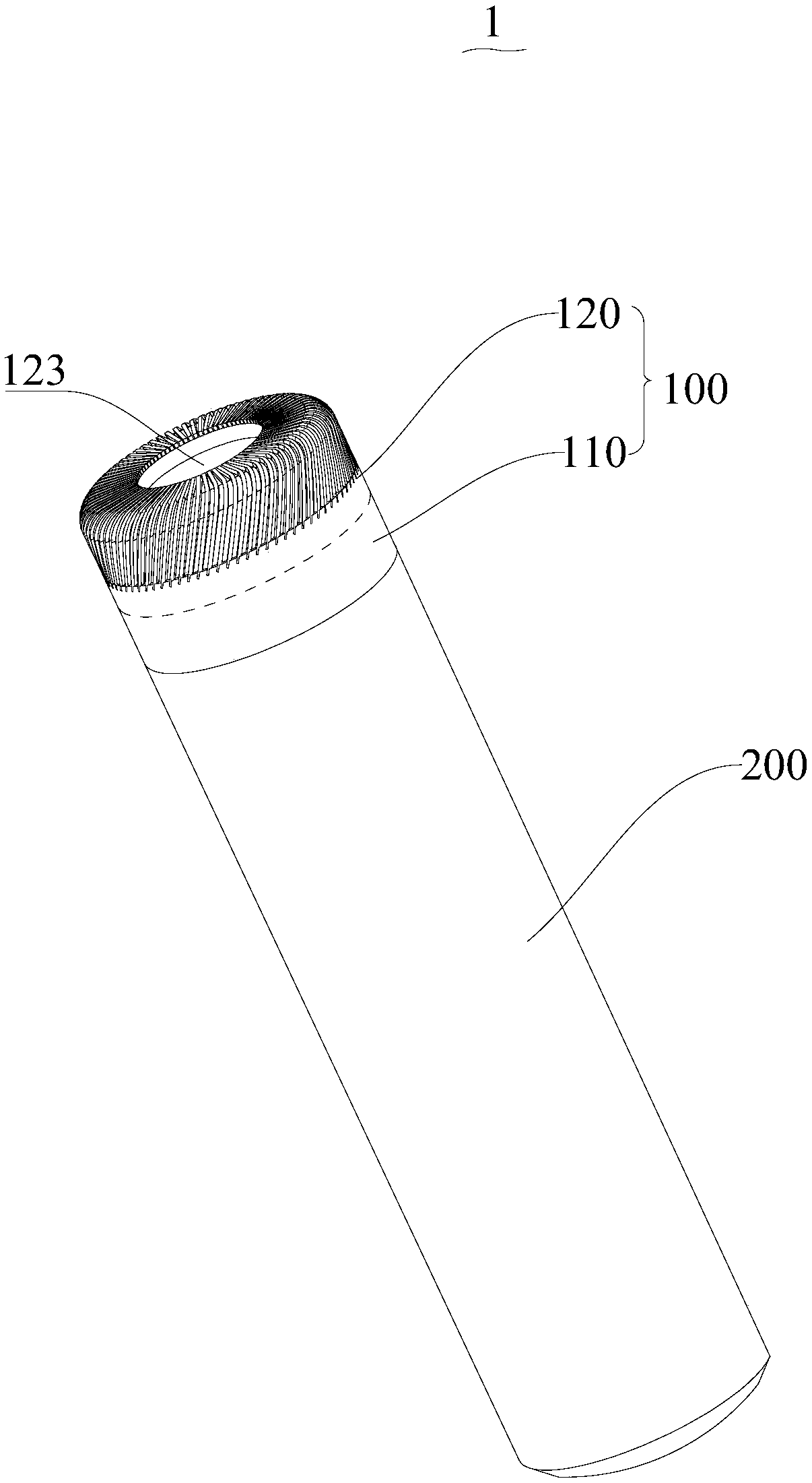
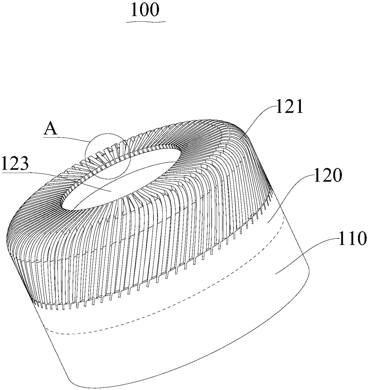
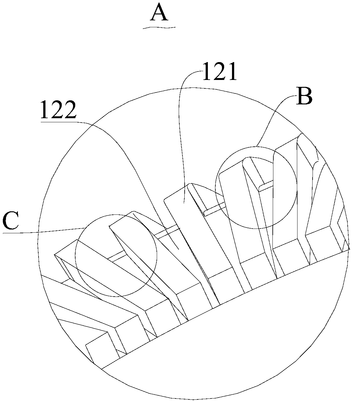
[0086] A kind of machining cutter, comprises polycrystalline diamond cutter head 100 and knife handle 200; Polycrystalline diamond cutter head 100 comprises base layer 110 and polycrystalline diamond layer 120, and one end of base layer 110 is fixedly connected with handle 200 by welding, The other end of the base layer 110 is sintered and pressed together with the polycrystalline diamond layer 120 to realize a fixed connection; at the end of the polycrystalline diamond layer 120 away from the base layer 110, 70 polycrystalline diamond cutting edges 121 are evenly distributed in a ring shape, adjacent polycrystalline diamond Chip flutes 122 are formed between the crystalline diamond cutting edges 121 . The polycrystalline diamond layer 120 has an end face and a side face connected with the end face, and 70 polycrystalline diamond cutting edges 121 are formed by cutting one by one on the polycrystalline diamond layer 120 by laser, so that the polycrystalline diamond layer 120 an...
Embodiment 2
[0093] A kind of machining cutter, comprises polycrystalline diamond cutter head 100 and knife handle 200; Polycrystalline diamond cutter head 100 comprises base layer 110 and polycrystalline diamond layer 120, and one end of base layer 110 is fixedly connected with handle 200 by welding, The other end of the base layer 110 is sintered and pressed together with the polycrystalline diamond layer 120 to realize a fixed connection; at the end of the polycrystalline diamond layer 120 away from the base layer 110, 62 polycrystalline diamond cutting edges 121 are evenly distributed in a ring shape, adjacent polycrystalline diamond Chip flutes 122 are formed between the crystalline diamond cutting edges 121 . The polycrystalline diamond layer 120 has an end face and a side connected to the end face, and 62 polycrystalline diamond cutting edges 121 are formed by cutting the polycrystalline diamond layer 120 one by one by laser, so that the polycrystalline diamond layer 120 and the 62 p...
Embodiment 3
[0101] A kind of machining cutter, comprises polycrystalline diamond cutter head 100 and knife handle 200; Polycrystalline diamond cutter head 100 comprises base layer 110 and polycrystalline diamond layer 120, and one end of base layer 110 is fixedly connected with handle 200 by welding, The other end of the base layer 110 is sintered and pressed together with the polycrystalline diamond layer 120 to realize a fixed connection; at the end of the polycrystalline diamond layer 120 away from the base layer 110, 56 polycrystalline diamond cutting edges 121 are evenly distributed in a ring shape, adjacent polycrystalline diamond Chip flutes 122 are formed between the crystalline diamond cutting edges 121 . The polycrystalline diamond layer 120 has an end face and a side face connected with the end face, and 56 polycrystalline diamond cutting edges 121 are formed by cutting one by one on the polycrystalline diamond layer 120 by laser, so that the polycrystalline diamond layer 120 an...
PUM
| Property | Measurement | Unit |
|---|---|---|
| width | aaaaa | aaaaa |
| depth | aaaaa | aaaaa |
| surface roughness | aaaaa | aaaaa |
Abstract
Description
Claims
Application Information
 - Generate Ideas
- Intellectual Property
- Life Sciences
- Materials
- Tech Scout
- Unparalleled Data Quality
- Higher Quality Content
- 60% Fewer Hallucinations
Browse by: Latest US Patents, China's latest patents, Technical Efficacy Thesaurus, Application Domain, Technology Topic, Popular Technical Reports.
© 2025 PatSnap. All rights reserved.Legal|Privacy policy|Modern Slavery Act Transparency Statement|Sitemap|About US| Contact US: help@patsnap.com


