
Control flow for manipulator of precision gear hobbing machine

A technology for controlling process and manipulators, which is applied to gear cutting machines, mechanical equipment, components with teeth, etc., can solve problems such as low production efficiency of automatic products, unstable system operation, and insufficient control process design of manipulators, etc., to achieve Improve the degree of automation and the effect of smooth operation

Inactive Publication Date: 2018-12-07
浙江屹立机器人科技有限公司
View PDF8 Cites 0 Cited by
  • Summary
  • Abstract
  • Description
  • Claims
  • Application Information

AI Technical Summary

Problems solved by technology

The characteristic is that various expected operations can be completed through programming, and the structure and performance have both the advantages of man and robot. The manipulator is the earliest industrial robot and the first modern robot. It can replace the heavy labor of people and It realizes the mechanization and automation of production, and can operate in harmful environments to protect personal safety. Therefore, it is widely used in machinery manufacturing, metallurgy, electronics, light industry and atomic energy. It is also widely used in the field of gear hobbing machines. It is currently used in customer gear hobbing machines The manipulator in the automatic loading and unloading of processed parts realizes automatic work through a set of program flow and according to the program flow. However, the control process design of the commonly used manipulator is not good enough, its degree of automation and product production efficiency are low, and the system The operation is also unstable, so it is necessary to redesign a control process of a precision hobbing machine manipulator that can improve the automation of the customer's equipment, product production efficiency and product quality, and make the entire system run smoothly, high-speed and precise

Method used


Image

  • Control flow for manipulator of precision gear hobbing machine

Examples


Embodiment Construction

[0027] In order to make the technical means, creative features, goals and effects achieved by the present invention easy to understand, the present invention will be further elaborated below in conjunction with illustrations and specific embodiments.

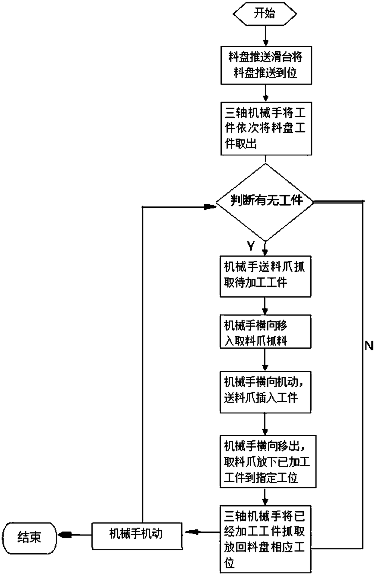
[0028] refer to figure 1 As shown, the control process for the manipulator of the precision gear hobbing machine includes the manipulator taking out the workpiece from the tray, the manipulator returning the processed workpiece to the tray, and judging whether there is a workpiece on the tray. The steps are as follows :

[0029] S1, start the manipulator drive;

[0030] S2. The tray pushing mechanism pushes the tray into place;

[0031] S3, the manipulator takes out the workpieces from the tray in turn;

[0032] S4. Judging whether there are workpieces, if the workpieces on the tray are not finished, proceed to the next step S5;

[0033] S5. The feeding claw of the manipulator grabs the workpiece to be processed;

[0034] S...


PUM


Abstract

The invention discloses a control flow for a manipulator of a precision gear hobbing machine. The control flow for the manipulator of the precision gear hobbing machine comprises the following steps:taking workpieces out from material trays in sequence by the manipulator, putting the machined workpieces back to the material trays by the manipulator, and judging whether the workpieces exist on thematerial trays or not, wherein 2 to 5 material trays can be placed into a lifting mechanism, and each layer has a detecting mechanism for detecting whether the material trays exist on the corresponding layer or not; and lifting the material trays detected to be full of materials to designated positions by the lifting mechanism, and enabling a matrix material tray belt line to start rotate forwards to feed rectangular material trays to the material tray belt line of a three-axis manipulator which is rotating forwards. The control flow of the manipulator is mainly applied to automatic feeding and discharging of components machined by a gear hobbing machine of a client; the manipulator of the gear hobbing machine is controlled by the flow, and therefore the automation degree of client equipment, the production efficiency of products and the quality of the products can be improved; and a plurality of complicated transmission modes, such as pneumatic and servo modes, are comprehensively utilized, so that the overall system operates stably, rapidly and precisely.

Description

technical field [0001] The invention relates to the field of gear hobbing machine manipulator control, in particular to a control flow for precision gear hobbing machine manipulators. Background technique [0002] A manipulator is an automatic operating device that can imitate certain movement functions of the human hand and arm to grab, carry objects or operate tools according to a fixed program. The characteristic is that various expected operations can be completed through programming, and the structure and performance have both the advantages of man and robot. The manipulator is the earliest industrial robot and the first modern robot. It can replace the heavy labor of people and It realizes the mechanization and automation of production, and can operate in harmful environments to protect personal safety. Therefore, it is widely used in machinery manufacturing, metallurgy, electronics, light industry and atomic energy. It is also widely used in the field of gear hobbing ...

Claims


Application Information

Patent Timeline
Patent Type & Authority Applications(China)
IPC IPC(8): B23F23/00B23F23/04
Inventor 许振红
Owner 浙江屹立机器人科技有限公司
Learn More