Copper tube cutting device

A technology for cutting devices and copper pipes, which is applied in the direction of pipe shearing devices, shearing devices, positioning devices, etc., can solve the problems of unfavorable long U pipes and air-conditioning heat exchange parts installation and coordination, flanging, and unequal nozzles, and achieve Avoid the unstable cutting position and avoid the effect of rubbing against each other

Inactive Publication Date: 2018-11-27
GREE ELECTRIC APPLIANCES WUHAN +1
View PDF7 Cites 1 Cited by
  • Summary
  • Abstract
  • Description
  • Claims
  • Application Information

AI Technical Summary

Problems solved by technology

[0003] At present, due to the limitations of the manufacturing process, the long U tubes cut by the existing cutting device have problems such as uneven nozzles, flanging, and tube beating. On the other hand, the nozzle of the long U tube will scrape on the inner wall of the air conditioner heat exchange part, and then scrape aluminum chips and aluminum powder from the inner wall, and remain at the nozzle of the long U tube Aluminum shavings and aluminum powder will cause problems such as welding leakage when welding small elbows. Therefore, in order to reduce the risk of welding leakage caused by scraping aluminum shavings and aluminum powder at the copper pipe nozzle, a new type of copper pipe cutting device is designed. appears to be particularly important

Method used


Image

  • Copper tube cutting device
  • Copper tube cutting device
  • Copper tube cutting device

Examples


Embodiment Construction

[0028] The technical solutions in the embodiments of the present invention will be clearly and completely described below in conjunction with the accompanying drawings in the embodiments of the present invention. Obviously, the described embodiments are only a part of the embodiments of the present invention, rather than all the embodiments. Based on the embodiments of the present invention, all other embodiments obtained by those of ordinary skill in the art without creative work shall fall within the protection scope of the present invention.

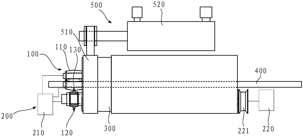
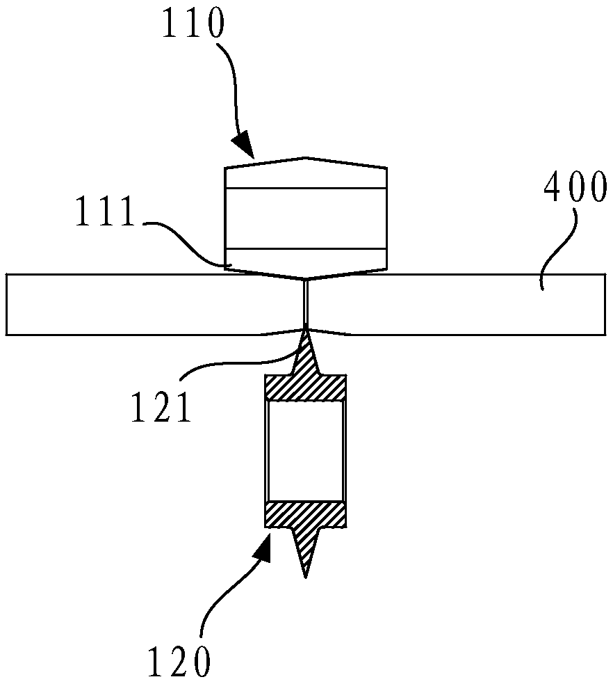
[0029] Such as figure 1 , figure 2 as well as image 3 As shown, a copper pipe cutting device includes a frame 300, and also includes a cutter head 121 mechanism 100 and a driving mechanism 200 installed on the frame 300, wherein:

[0030] The knife head 121 mechanism 100 includes a cutting knife 120 and a cutting table 110. The knife head 121 of the cutting knife 120 has a chamfer of 25°-40°. The cutting table 110 is arranged opposite to...


PUM


Abstract

The invention relates to the technical field of cutting and processing, and discloses a copper tube cutting device. The copper tube cutting device includes a rack, and a knife head mechanism and a driving mechanism mounted on the rack, wherein the knife head mechanism comprises a cutting knife and a cutting table, and the head chamfer of the cutting knife is 25 degrees-40 degrees, the cutting table is opposite to the cutting knife, and the opposite end face of the cutter head is conic, the driving mechanism is rotatably connected with the knife head mechanism, and can drive the knife head mechanism to move along the direction perpendicular to the copper tube to be cut, and drive the knife head mechanism to rotate when the knife head mechanism is clamped tightly to the copper tube to be cut, and the knife head mechanism is clamped to the copper pipe to be cut while cutting, and the unstable cutting position is avoided, the driving mechanism drives the knife head mechanism to move, and simultaneously drives the knife head mechanism to rotate, the cutting knife and the cutting table squeeze the copper tube, the pipe mouth is internal contraction, while the pipe wall of the copper tubeis extruded into an inward tilt cone, so that the tube will not touch the finned tube when wearing the tube, thereby solving the problem of scraping aluminium scraps and aluminum powder at the mouthof long U copper pipe.

Description

Technical field [0001] The invention relates to the technical field of cutting processing, in particular to a copper tube cutting device. Background technique [0002] In the field of cutting processing technology, when the long straight section of copper pipe is cut into a certain length and then applied to products such as air conditioners and solar water heaters, the copper pipes used in the heat exchange parts of air conditioners use long U pipes to pass through the pipes. The other end is welded in the form of a small elbow to realize the connection of the copper tube of the entire heat exchange part. [0003] At present, due to the limitation of the production and manufacturing process, the long U tube cut by the existing cutting device has problems such as uneven tube mouth, external flanging, and pipe running. The heat exchanger of the air conditioner is not conducive to the long U tube when the long U tube is worn. The installation of the tube and the air conditioner heat...

Claims


Application Information

Patent Timeline
IPC IPC(8): B23D21/04B23Q3/00
CPCB23D21/04B23Q3/00B23Q2703/10
Inventor 刘波刘爽胡建辉康扬张佳万雪兵
Owner GREE ELECTRIC APPLIANCES WUHAN
Why Eureka
Try Eureka