Method for preventing water purification diaphragm from being damaged

A technology of water purification membrane and carrying box, which is applied in the direction of chemical instruments and methods, multi-stage water treatment, water/sewage treatment, etc., and can solve the problems such as the need for protection of water purification membrane components, so as to increase the pressure and prevent loosening and unloading , the effect of reducing the contact surface

Inactive Publication Date: 2018-11-30
龚平
View PDF3 Cites 0 Cited by
  • Summary
  • Abstract
  • Description
  • Claims
  • Application Information

AI Technical Summary

Problems solved by technology

[0005] The purpose of the present invention is to provide a method for avoiding damage to the water purification membrane, and to solve the problem that the water purification membrane assembly needs to be protected during storage and transportation

Method used


Image

  • Method for preventing water purification diaphragm from being damaged
  • Method for preventing water purification diaphragm from being damaged
  • Method for preventing water purification diaphragm from being damaged

Examples


Embodiment 1

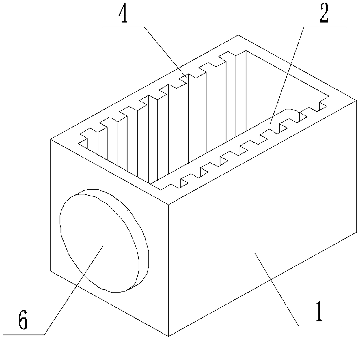
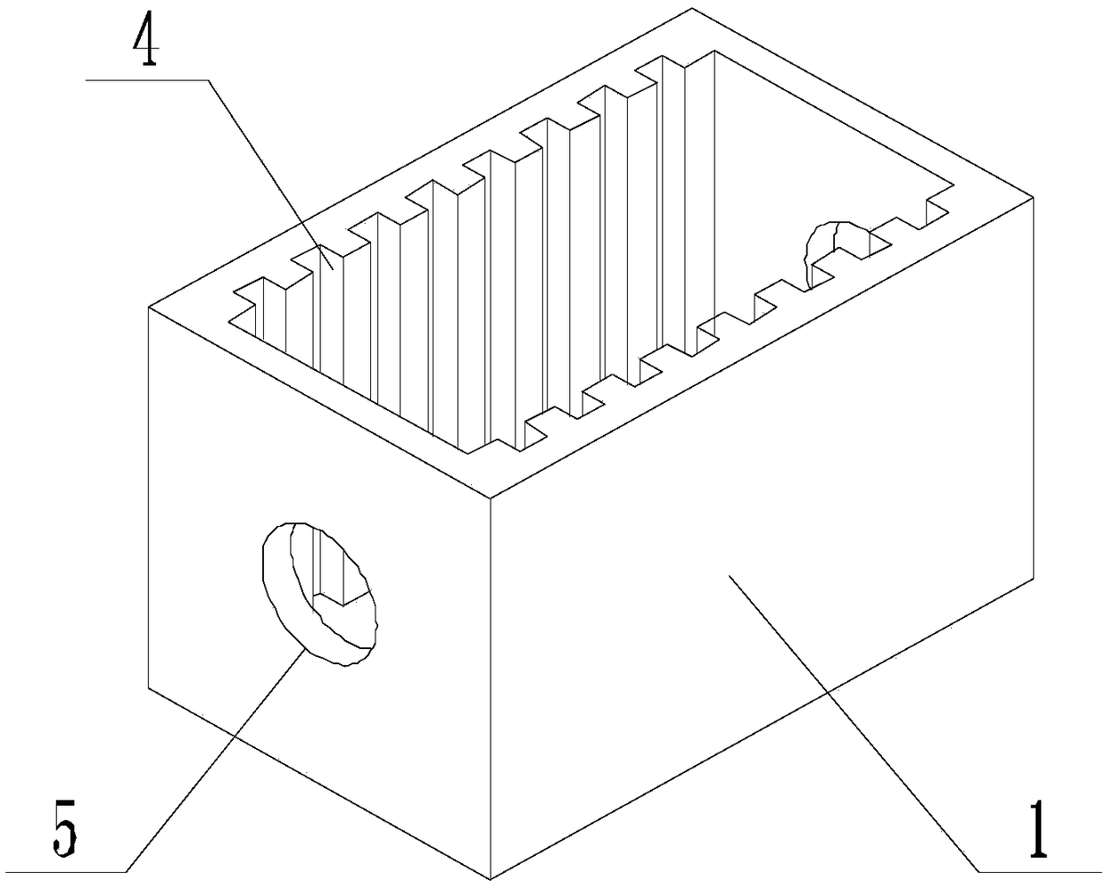
[0035] Such as Figure 1-Figure 5 As shown, the present invention avoids the method that water purification membrane is damaged, comprises the steps:

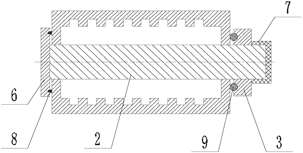
[0036] Step A: Loosen the nut 3 until the nut 3 retreats from the screw rod 2;

[0037] Step B: move the stop plate 6 away from the carrying box 1 until the screw 2 withdraws from the through hole 5;

[0038] Step C: Place each water purification membrane assembly in the carrying box 1 in turn, so that the two ends of the water purification membrane assembly are respectively located in a pair of opposite guide grooves 4, and the bottom of the water purification membrane assembly is in contact with the carrying box 1 The bottom of the cavity wall is in contact, and the through hole on the water purification membrane assembly is parallel to the axis of the through hole 5 on the carrying box 1;

[0039] Step D: Pass the end of the screw 2 away from the retaining plate 6 through the through hole 5 on one side of the carrying box ...

Embodiment 2

[0046] Preferably, the distance between the bottom of the guide groove 4 on the inner wall of one side and the bottom of the corresponding guide groove 4 on the other side of the groove wall is consistent with the width of the water purification membrane assembly, and the through hole on the carrying box 1 5 The distance from the bottom of the inner cavity wall of the carrying box 1 is consistent with the size of the through hole on the water purification membrane assembly from the bottom of itself.

Embodiment 3

[0048] An annular groove is arranged on the side of the baffle plate 6 close to the carrier box 1, the axis of the annular groove coincides with the axis of the baffle plate 6, and a sealing ring 8 is embedded in the annular groove, when the baffle plate 6 and the nut 3 are in contact with the bearing box 1, when the nut 3 is screwed relative to the screw rod 2, the sealing ring 8 can be compressed and deformed.

[0049] The compression deformation of the sealing ring 8 increases the axial pressure of the thread between the nut 3 and the screw rod 2 to prevent the nut 3 from being loosened and improves the stability of the present invention.


PUM


Abstract

The invention discloses a method for preventing a water purification diaphragm from being damaged. The method comprises the following steps: step A: loosening and removing a nut from a screw; step B:moving a baffle away from a bearing box until the screw completely leaves a through hole; step C: placing water purification diaphragm assemblies in the bearing box in turn, and keeping two ends of each water pufiication diaphragm assembly placed in a pair of guide grooves opposite to each other; and step D: enabling the end, away from the baffle, of the screw to pass through the through hole in one side of the bearing box, then to pass through the water purification diaphragm assemblies, and to pass through the through hole in the other side of the bearing box, and then enabling the end of the screw to be in threaded connection with the nut. Compared with simple stacking of water purification diaphragm assemblies, the water purification diaphragm assemblies are borne in the method, thus friction and scratch of the water purification diagram assemblies caused by small dust particles on the surface of the water purification diagram assemblies are avoided and self-supporting components are prevented from being damaged by external forces due to the absence of a protective shell.

Description

technical field [0001] The invention relates to the field of filter membranes, in particular to a method for avoiding damage to water purification membranes. Background technique [0002] The filter membrane is used for the separation and concentration of solutes in the treatment solution, and is also commonly used for the separation of colloidal suspensions. Membrane water treatment is a solid-liquid separation technology. It uses membrane pores to filter water and retain impurities in the water without chemical changes. The technology is simple and easy to handle. The filter membrane is classified by the size of the intercepted raw water particles, and the membrane pores are divided into microfiltration membrane (MF), ultrafiltration membrane (UF), nanofiltration membrane (NF) and reverse osmosis membrane (RO) from coarse to fine. The MF membrane has a pore size of 0.05um or more, or a molecular weight of 1000 or more, and is aimed at removing colloids and high-molecular ...

Claims


Application Information

Patent Timeline
Patent Type & Authority Applications(China)
IPC IPC(8): C02F1/44
CPCC02F1/44C02F2201/002C02F2201/004C02F2301/08C02F2303/14
Inventor 龚平
Owner 龚平
Why Eureka
Try Eureka