
Liquid crystaL dispLay paneL and dispLay device

A liquid crystal display panel and area technology, applied in static indicators, instruments, nonlinear optics, etc., can solve the problem of low reflectivity of liquid crystal display panels

Pending Publication Date: 2018-11-23
SHANGHAI TIANMA MICRO ELECTRONICS CO LTD
View PDF8 Cites 10 Cited by
  • Summary
  • Abstract
  • Description
  • Claims
  • Application Information

AI Technical Summary

Problems solved by technology

[0005] Embodiments of the present invention provide a liquid crystal display panel and a display device to solve the technical problem of low reflectivity of liquid crystal display panels in the prior art

Method used


Image

  • Liquid crystaL dispLay paneL and dispLay device
  • Liquid crystaL dispLay paneL and dispLay device
  • Liquid crystaL dispLay paneL and dispLay device

Examples


Embodiment Construction

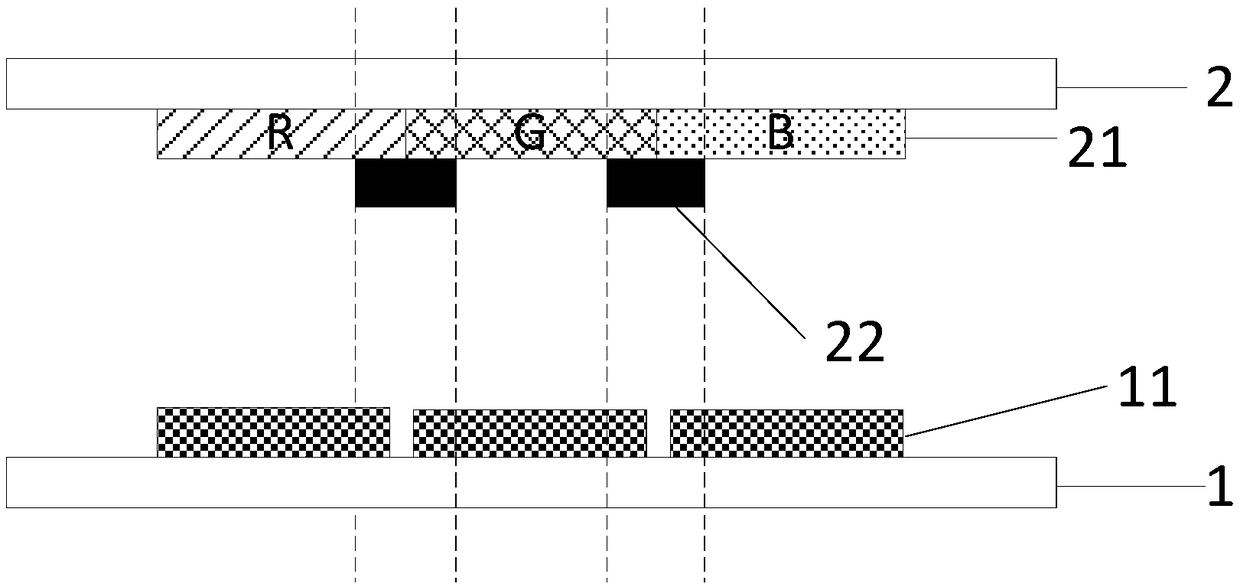
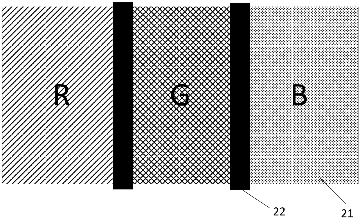
[0037] In order to alleviate the problem of color mixing between adjacent color resistances of different colors, such as figure 1 with figure 2 As shown, generally, a black matrix 22 is provided between the color resists 21 of different colors to cover the overlapping area between the color resists 21 of different colors, so as to prevent color mixing and affect the display effect of the display panel. However, since the arrangement of the black matrix 22 will cover part of the reflective metal 11, that is, the orthographic projection of the black matrix 22 on the array substrate 1 overlaps with the orthographic projection of the reflective metal 11 on the array substrate 1, which reduces the reflection. The effective reflective area of ​​the metal 11 reduces the utilization rate of the reflective metal 11, thereby reducing the reflectivity. Therefore, how to increase reflectivity while preventing color mixing between adjacent color resists of different colors is an urgent p...


PUM


Abstract

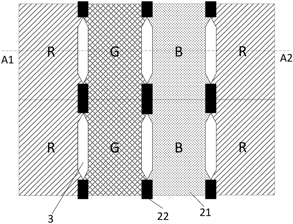
The invention discLoses a Liquid crystaL dispLay paneL and a dispLay device. The Liquid crystaL dispLay paneL comprises an array substrate, an opposite substrate, a refLective metaL, muLtipLe coLor resistors and a bLack matrix, wherein the array substrate and the opposite substrate are arranged oppositeLy, the refLective metaL is Located at the side, facing the opposite substrate, of the array substrate, the coLor resistors are Located at the side, facing the array substrate, of the opposite substrate and arranged in an array, and the bLack matrix is Located at the side, facing the array substrate, of the opposite substrate; through a mode that Long-strip-shaped first opening areas extending in a second direction are arranged among the coLor resistors with different coLors arranged in a first direction, the bLack matrix and the first opening areas are arranged aLternateLy in the second direction, the area of the bLack matrix shieLding the refLective metaL is reduced whiLe the phenomenon of coLor mixing caused by every two adjacent coLor resistors with the different coLors is reLieved, the effective refLective area of the refLective metaL is increased, and the refLectivity is improved.

Description

technical field [0001] The invention relates to the field of display technology, in particular to a liquid crystal display panel and a display device. Background technique [0002] Liquid crystal display panels in the prior art can be divided into transmissive, reflective and transflective types according to the form of the light source provided. Among them, the reflective type does not need to be equipped with a backlight, and the transflective type only needs to be provided with a backlight in the transmissive area. Source, the power consumption of the liquid crystal display panel can be greatly reduced by reducing the setting of the backlight source, therefore, reflective and transflective liquid crystal display panels are attracting more and more attention. [0003] Among the current liquid crystal display panels, the reflective and transflective liquid crystal display panels rely on the reflective metal on the array substrate to reflect the external light source, so the...

Claims


Application Information

Patent Timeline
IPC IPC(8): G02F1/1335
CPCG02F1/133512G02F1/133514G02F1/133553G02F1/133555G09G3/3607G09G2320/0209G02F1/13394G02F1/134336G02F1/13439G02F1/136286G02F1/1368G02F2201/123G02F2203/01G02F2203/02G09G3/3674G09G3/3685
Inventor 张欢喜孔祥建谢明王磊
Owner SHANGHAI TIANMA MICRO ELECTRONICS CO LTD
Learn More