
Solar cell structure

A technology for solar cells and solar cells, applied in the field of solar cells, can solve the problems of rising fragmentation rate, cell fragmentation, power loss, etc., and achieve the effect of reducing usage and improving power

Inactive Publication Date: 2015-09-23
ZHEJIANG JINKO SOLAR CO LTD +1
View PDF3 Cites 9 Cited by
  • Summary
  • Abstract
  • Description
  • Claims
  • Application Information

AI Technical Summary

Problems solved by technology

[0003] 1. The components made of cells must be welded with ribbons, and the stress of welding will cause cell fragments;
[0004] 2. The welding temperature will destroy the PN junction of the cell;
[0005] 3. The shading area of ​​the welding strip is relatively large, and the resulting power loss is 3% to 4%;
[0006] 4. When the solar cell with this structure is formed into a module, a certain gap must be maintained between the cell and the cell directly for the bending of the ribbon. If the distance is too small, the fragmentation rate will increase.

Method used


Image

  • Solar cell structure
  • Solar cell structure
  • Solar cell structure

Examples


Embodiment Construction

[0026] As mentioned in the background art section, in the production of components in the prior art, it is necessary to use solder ribbons to connect the front side of a cell to the back side of an adjacent cell to form a series circuit. This design has the following characteristics: the components made of cells must be welded with ribbons, and the stress of welding will cause fragments of the cells; the temperature of welding will destroy the PN junction of the cells; The power loss caused by this is 3% to 4%. When the solar cell with this structure is formed into a module, a certain gap must be maintained between the cell and the cell directly for the bending of the solder ribbon. If the distance is too small, the fragmentation rate will increase.

[0027] Based on this, an embodiment of the present invention provides a solar cell structure, including a solar cell sheet, a front electrode is provided on the front side of the solar cell sheet, a back electrode and a back elect...


PUM


Abstract

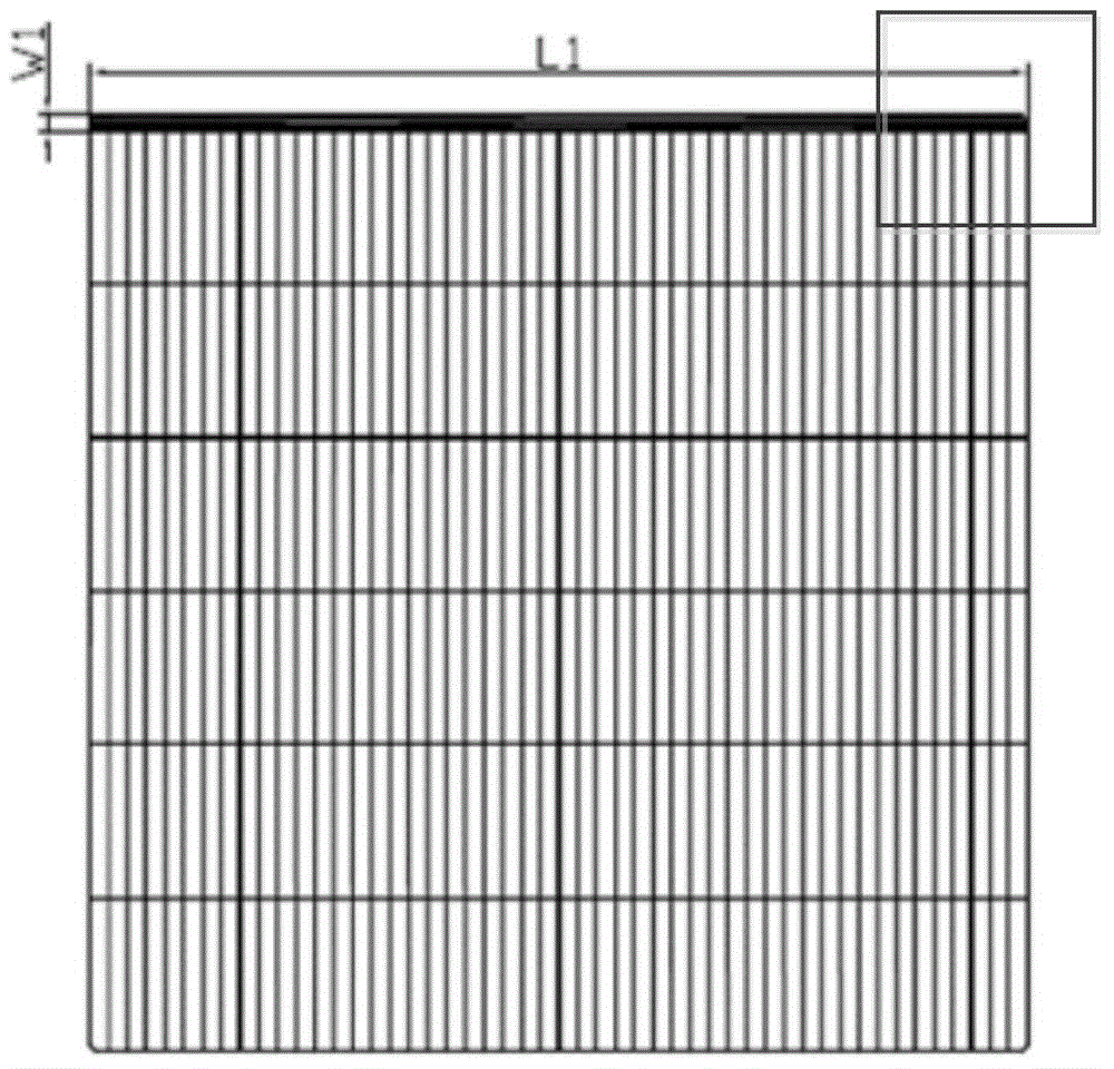
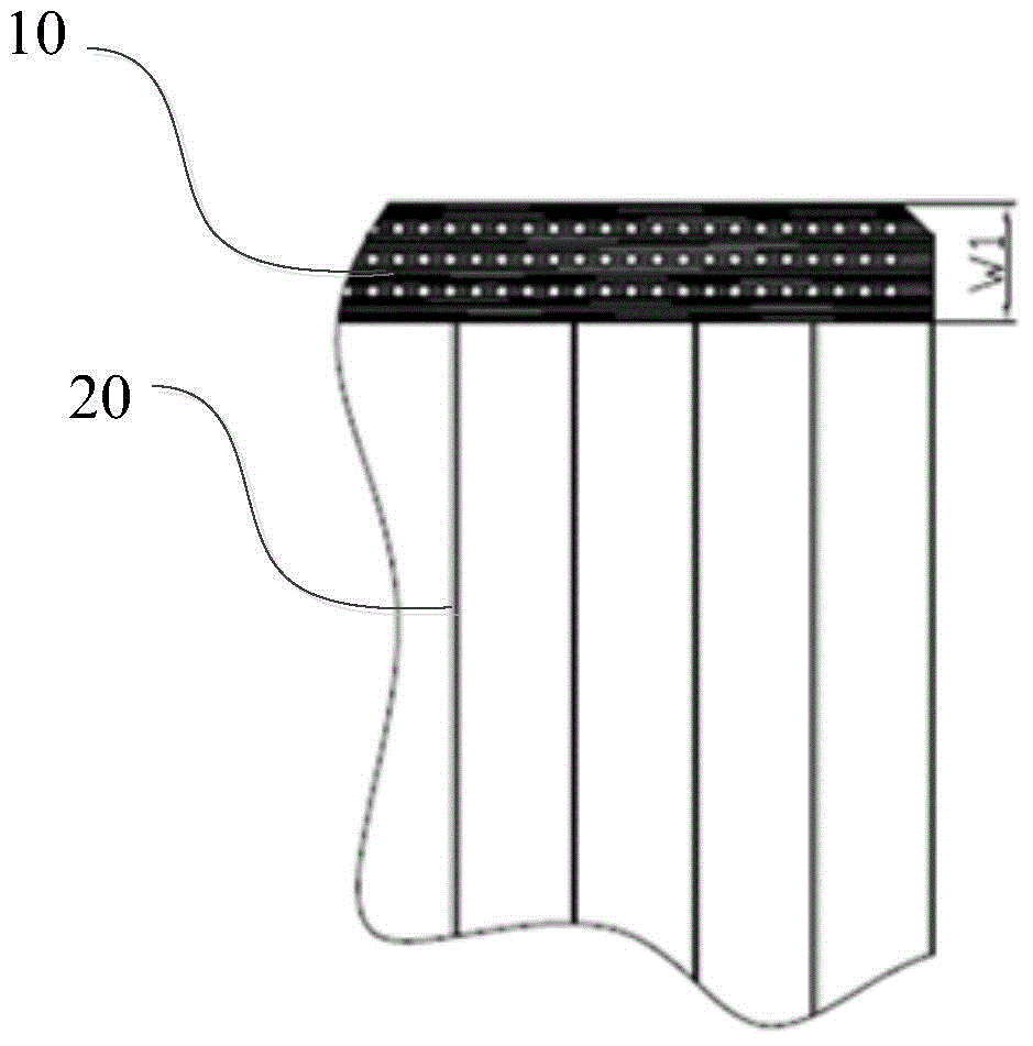
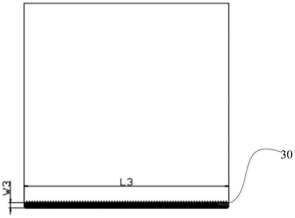
The invention discloses a solar cell structure which comprises solar cell pieces, each solar cell piece is provided with a positive electrode at the front side and a back electrode and a back field structure at the back side, the positive electrode comprises a main grid line, a plurality of secondary grid lines perpendicular to the main grid line and a plurality of slim grid lines parallel to the main grid line, the main grid line is arranged at an upper edge of the solar cell piece, the back electrode is arranged at a lower edge of the solar cell piece and is in parallel to the main grid line, the area of the back field structure is partially overlapped with the area of the back electrode, and the main grid lines of adjacent solar cell pieces are laminated with the back electrode. By adopting a module fabricated from the solar cell structure, the main grid lines of adjacent solar cell pieces are laminated with the back electrode, an overlapping area exists, thus, a soldering strip is avoided to connect the front side and the back side, the usage amount of the soldering strips is reduced, shading area is reduced, the light absorption efficiency of the module is improved, and the module power is enhanced.

Description

technical field [0001] The invention belongs to the technical field of solar cells, and in particular relates to a solar cell structure. Background technique [0002] A solar cell is a device that directly converts light energy into electrical energy based on the photovoltaic effect. The manufacturing process of conventional structural crystalline silicon solar cells includes texturing, diffusion, backside etching, silicon nitride deposition, screen printing, and sintering. Conventional crystalline silicon solar cells generally use more than one busbar to be centered on the surface of the cell, the sub-grid lines are vertically and evenly distributed in the center of the main grid, and the position of the back electrode is consistent with the positive electrode busbar, so that the stress damage of the ribbon is reduced to minimum. In current module production, it is necessary to use ribbons to connect the front of a cell to the back of an adjacent cell to form a series cir...

Claims


Application Information

Patent Timeline
Patent Type & Authority Applications(China)
IPC IPC(8): H01L31/0224H01L31/05
CPCY02E10/50H01L31/022433H01L31/0508
Inventor 袁占强
Owner ZHEJIANG JINKO SOLAR CO LTD
Learn More