
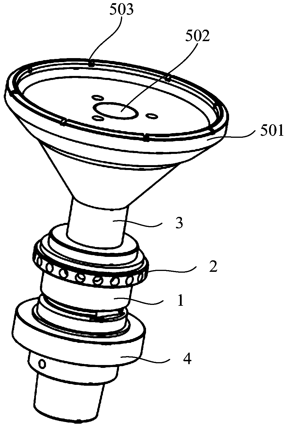
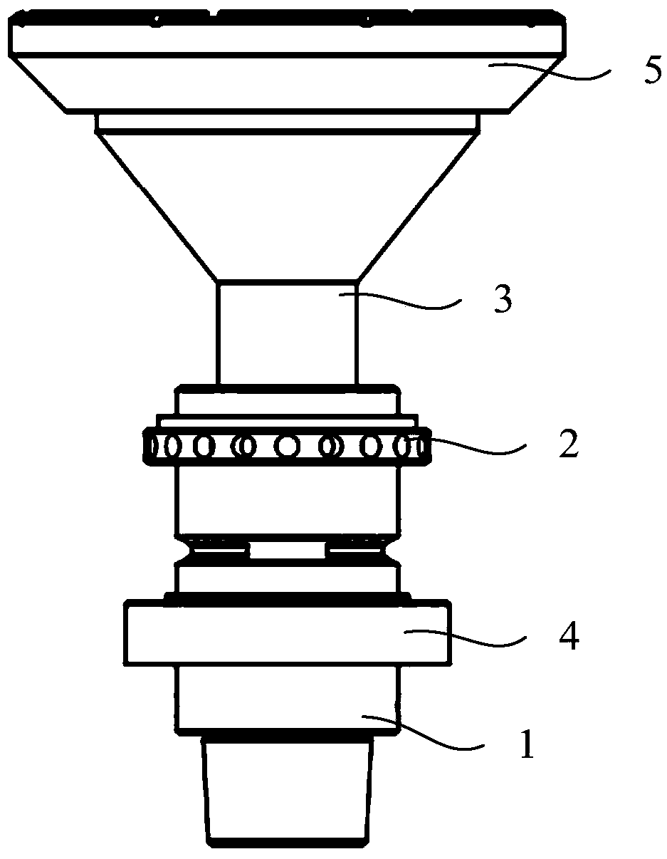
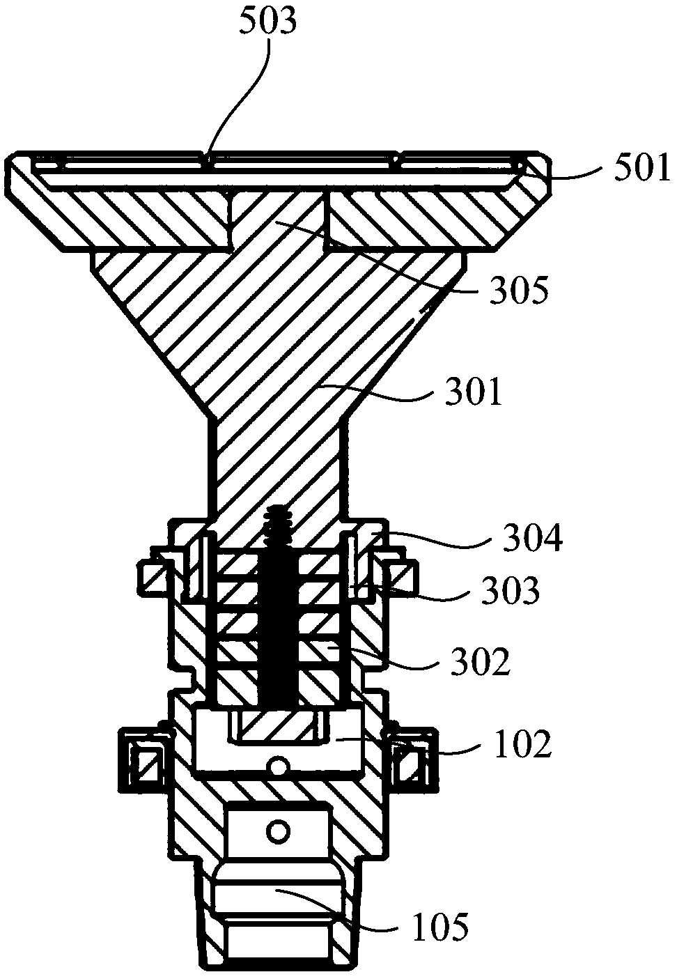
Dynamic balance ultrasonic cutterhead

An ultrasonic and cutter head technology, which is applied in the direction of vibrating fluid, grinding head, manufacturing tools, etc., can solve the problems of ultrasonic cutter head rotation imbalance, poor processing accuracy, etc., and achieve the effect of reducing mechanical failure and improving processing accuracy

Pending Publication Date: 2018-11-23
CONPROFE TECH GRP CO LTD +1
View PDF3 Cites 0 Cited by
  • Summary
  • Abstract
  • Description
  • Claims
  • Application Information

AI Technical Summary

Problems solved by technology

[0008] The purpose of this application is to provide a dynamically balanced ultrasonic cutter head to solve the technical problem of poor machining accuracy caused by the unbalanced rotation of the ultrasonic cutter head in the prior art.

Method used


Image

  • Dynamic balance ultrasonic cutterhead
  • Dynamic balance ultrasonic cutterhead
  • Dynamic balance ultrasonic cutterhead

Examples


Embodiment Construction

[0048] The technical solutions of the present invention will be clearly and completely described below in conjunction with the accompanying drawings. Apparently, the described embodiments are some of the embodiments of the present invention, but not all of them.

[0049] The components of the embodiments of the invention generally described and shown in the figures herein may be arranged and designed in a variety of different configurations. Accordingly, the following detailed description of the embodiments of the invention provided in the accompanying drawings is not intended to limit the scope of the claimed invention, but merely represents selected embodiments of the invention.

[0050] Based on the embodiments of the present invention, all other embodiments obtained by persons of ordinary skill in the art without making creative efforts belong to the protection scope of the present invention.

[0051] In the description of the present invention, it should be noted that the...


PUM

PropertyMeasurementUnit
Diameteraaaaaaaaaa

Abstract

The invention relates to the technical field of machining and particularly relates to a dynamic balance ultrasonic cutterhead. The dynamic balance ultrasonic cutterhead comprises a knife handle, a cutterhead, a dynamic balance ring, an ultrasonic transducer and wireless transmission transmitting and receiving devices; the knife handle comprises a knife handle main body and an assembly joint; the dynamic balance ring is sleeved on the knife handle main body and is used for adjusting the center-of-gravity position of the whole cutterhead; an accommodating cavity is formed at one end, away from the assembly joint, of the knife handle main body; the ultrasonic transducer is positioned in the accommodating cavity; the wireless transmission transmitting device is positioned on the main shaft; the wireless transmission receiving device is sleeved on the knife handle main body and is connected with the ultrasonic transducer. According to the dynamic balance ultrasonic cutterhead provided by the invention, through the ultrasonic transducer arranged in the knife handle, the cutterhead generates high-frequency vibration so as to realize ultrasonic processing. Moreover, the dynamic balance ring adjusts the overall dynamic balance performance of the cutterhead component so as to reduce mechanical failure.

Description

technical field [0001] The present application relates to the technical field of machine tool processing, in particular to a dynamically balanced ultrasonic cutterhead. Background technique [0002] As the connection between the machine tool spindle and the cutting tool, the tool holder plays the role of rigidly connecting the machine tool spindle and the cutting tool; in order to adapt to the rotary ultrasonic machining, people integrate the vibration system into the tool holder to obtain an ultrasonic tool holder. [0003] However, the structure of the traditional ultrasonic tool holder integrated with the vibration system is not stable enough, and its horn is prone to tilt after collision, thereby increasing the circular runout of the horn and affecting the dynamic balance of the horn, resulting in low machining accuracy of the ultrasonic tool handle. Poor, short service life. [0004] TWM372763U discloses an ultrasonic vibration tool module, the first coil is fixed to t...

Claims


Application Information

Patent Timeline
IPC IPC(8): B24B41/047B24B41/053B24B41/04B24B45/00B24B1/04B24D7/00B06B1/06B06B3/02
CPCB06B1/06B06B3/02B24B1/04B24B41/042B24B41/0475B24B41/053B24B45/006B24D7/00
Inventor 颜炳姜李伟秋林一松
Owner CONPROFE TECH GRP CO LTD
Learn More