
Sectional composite dense net structure carotid artery stent

A carotid artery, segmented technology, applied in the field of segmented composite dense mesh structure carotid artery stent, can solve the problem that the blocking effect of debris is not very ideal, and achieve the effect of not easy to break, uniform pressure, and dense mesh

Inactive Publication Date: 2018-11-20
SHANGHAI CHANGHAI HOSPITAL
View PDF13 Cites 1 Cited by
  • Summary
  • Abstract
  • Description
  • Claims
  • Application Information

AI Technical Summary

Problems solved by technology

However, if the pores of the small-pore network tube are too small, it will have a great blocking effect on the blood flowing from the common carotid artery to the external carotid artery. On the contrary, if the pores of the small-pore network tube are larger, its blocking effect on debris is not ideal.

Method used


Image

  • Sectional composite dense net structure carotid artery stent
  • Sectional composite dense net structure carotid artery stent
  • Sectional composite dense net structure carotid artery stent

Examples


Embodiment 1

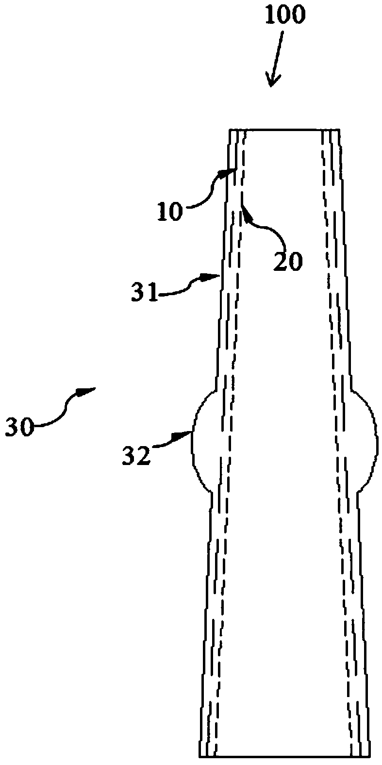
[0031] figure 1 It is a structural schematic diagram of a carotid artery stent with a segmented composite dense mesh structure in Embodiment 1 of the present invention.

[0032] Such as figure 1 As shown, the carotid artery stent 100 with segmented composite dense mesh structure in this embodiment includes a first support tube 10 , a second support tube 20 and a membrane tube 30 .

[0033] figure 2 is a schematic structural view of the first support tube in Embodiment 2 of the present invention.

[0034] Such as figure 2 As shown, the first support tube 10 is in the shape of a tapered hollow tube matching the shapes of the common carotid artery 2 and the internal carotid artery 3 , and is used to be placed in the common carotid artery 2 and the internal carotid artery 3 to play a supporting role. The taper of the first support tube 10 is α, 2.29°≤α≤3.81°. In this embodiment, the taper of the first support tube 10 is 2.29°.

[0035] The first support tube 10 is made o...

Embodiment 2

[0062] Figure 5 It is a structural schematic diagram of a carotid artery stent with a segmented composite dense mesh structure in Embodiment 2 of the present invention.

[0063] Such as Figure 5 As shown, the carotid artery stent 200 with segmented composite dense mesh structure in this embodiment includes a first support tube 210 and a membrane tube 220 .

[0064] The first support tube 210 is in the shape of a tapered hollow tube matching the shapes of the common carotid artery 2 and the internal carotid artery 3 , and is used to be placed in the common carotid artery 2 and the internal carotid artery 3 to play a supporting role. The taper of the first support tube 210 is α, 2.29°≤α≤3.81°. In this embodiment, the taper α of the first support tube 210 is 2.29°.

[0065] Figure 6 is a schematic structural view of the first support tube in Embodiment 2 of the present invention.

[0066] Such as Figure 6 As shown, the first support tube 210 is a tube with a mesh struct...


PUM

PropertyMeasurementUnit
The inside diameter ofaaaaaaaaaa
Lengthaaaaaaaaaa

Abstract

The invention provides a sectional composite dense net structure carotid artery stent used for being arranged at a divaricate structure of the internal carotid and external carotid artery connected with the common carotid artery so as to treat carotid artery stenosis. The carotid artery stent is characterized by comprising a first supporting tube and a membrane tube, wherein the first supporting tube is in the shape of a conical hollow tube matched with the shapes of the common carotid artery and the internal carotid and is used for being arranged in the common carotid artery and the internalcarotid to further support the common carotid artery and the internal carotid; the membrane tube is arranged on the outer wall of the first supporting tube in a sleeving manner and comprises two straight tube sections and an annular protrusion section connected with the two straight tube sections; the first supporting tube is a tube of a mesh structure made from memory metal wires; the wall thickness of the annular protrusion section is smaller than that of the straight tube section.

Description

technical field [0001] The invention relates to a carotid artery stent, in particular to a segmented composite dense mesh structure carotid artery stent. Background technique [0002] Cerebrovascular disease is a major disease that threatens human health today, and it is the third leading cause of death after cardiovascular diseases and tumors. Carotid artery stenosis is the main risk factor and etiological basis of ischemic cerebrovascular disease, and 25% of ischemic strokes are related to carotid artery stenosis or occlusion. [0003] Such as Figure 7 As shown, the carotid artery 1 has a "Y"-shaped bifurcation structure, including the common carotid artery 2, the internal carotid artery 3, and the external carotid artery 4. The blood in the common carotid artery 2 flows into two bifurcations, the internal carotid artery 3 and the external carotid artery 4 respectively, wherein the blood in the internal carotid artery 3 mainly flows to the brain. The carotid artery sten...

Claims


Application Information

Patent Timeline
IPC IPC(8): A61F2/90A61F2/915
CPCA61F2/90A61F2/915A61F2002/91575A61F2210/0014
Inventor 魏小龙赵志青吴雅妮韩同磊孙羽东朱江景在平周建王金萍
Owner SHANGHAI CHANGHAI HOSPITAL
Learn More