
A monitoring system and method for monitoring equipment faults

A technology for equipment failure and monitoring systems, applied in general control systems, control/regulation systems, comprehensive factory control, etc., can solve problems such as low efficiency, complex environment, and increased difficulty of inspection, and achieve the effect of improving accuracy

Active Publication Date: 2021-08-03
CHENGDE JIANLONG SPECIAL STEEL
View PDF10 Cites 0 Cited by
  • Summary
  • Abstract
  • Description
  • Claims
  • Application Information

AI Technical Summary

Problems solved by technology

[0002] In the manufacturing production line, industrial production equipment will be subjected to continuous vibration and shock, which will lead to wear and aging of equipment materials and parts, resulting in industrial equipment prone to failure, and when people realize the failure, many defective products may have been produced , and even the entire industrial equipment has collapsed and shut down, resulting in huge losses
[0003] The traditional maintenance is often to check the source of damage after the equipment is down, which is not only inefficient but also affects production
There are many production equipment in the factory and the environment is complex, which increases the difficulty of inspection
For example, the temperature detection method in related technologies can detect bearing damage, but many equipment failures are not accompanied by temperature changes, so the reliability of the temperature detection method is not high
As another example, the vibration accuracy of the vibration diagnosis method in the related art depends on the correctness of the diagnosis model, and the detection equipment is specific and cannot detect general-purpose equipment. Therefore, the vibration detection method has certain limitations.

Method used


Image

  • A monitoring system and method for monitoring equipment faults
  • A monitoring system and method for monitoring equipment faults
  • A monitoring system and method for monitoring equipment faults

Examples


Embodiment 1

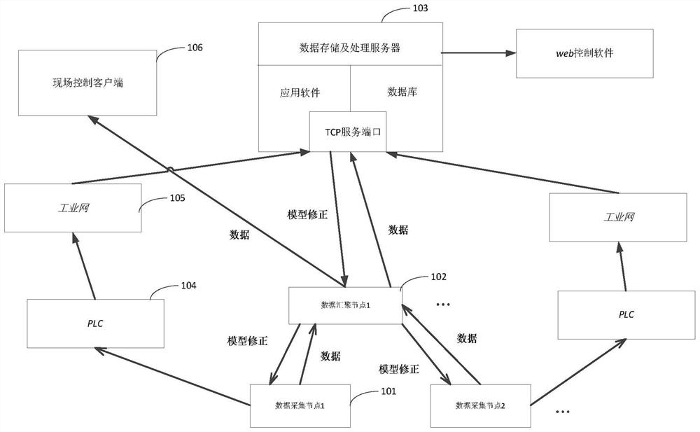
[0021] figure 1 It is a frame diagram of an equipment fault monitoring system provided by Embodiment 1 of the present invention. This embodiment is applicable to the detection of the health status of industrial equipment. Understandably, figure 1 The frame diagram of the monitoring system for equipment failure shown is only an example of the monitoring system, and the monitoring system may have more or fewer devices than shown in the figure, and two or more devices may be combined, Or it may have a different device configuration.

[0022] Such as figure 1 As shown, the monitoring system includes: a data acquisition node 101 , a data convergence node 102 , a data storage and processing server 103 , a programmable logic controller PLC 104 , an industrial network 105 and a field control client 106 .

[0023] The data acquisition node 101 is used to collect equipment state information of industrial equipment, predict the failure probability and time of failure of each industria...


PUM


Abstract

The invention discloses a monitoring system and a monitoring method for equipment faults. The monitoring system includes a data collection node for collecting equipment state information of industrial equipment, predicting the failure probability and time of failure of each industrial equipment according to the equipment state information through a preset prediction model, and calculating the failure probability, failure The occurrence time and equipment status information are sent to the data storage and processing server; the data storage and processing server is used to store the equipment status information, and display the equipment status information, failure probability and failure occurrence time in real time, according to the The device status information is used to correct the forecast model, and the corrected forecast model is sent to the data collection node. By adopting the above-mentioned technical solution, a system suitable for fault detection of various types of industrial equipment is provided, the applicability of the fault detection solution is expanded, and the accuracy and real-time performance are improved.

Description

technical field [0001] Embodiments of the present invention relate to intelligent detection technology, and in particular to a monitoring system and method for equipment faults. Background technique [0002] In the manufacturing production line, industrial production equipment will be subject to continuous vibration and shock, which will lead to wear and aging of equipment materials and parts, resulting in industrial equipment prone to failure, and when people realize the failure, many defective products may have been produced , Even the entire industrial equipment has collapsed and shut down, causing huge losses. [0003] The traditional maintenance is often to check the source of damage after the equipment is down due to failure, which is not only inefficient but also affects production. The factory has many production equipments and complex environment, which increases the difficulty of inspection. For example, the temperature detection method in the related art can det...

Claims


Application Information

Patent Timeline
Patent Type & Authority Patents(China)
IPC IPC(8): G05B19/418
CPCG05B19/4185G05B2219/31088Y02P90/02
Inventor 张泽光李若飞刘任栋张志柏郭佳
Owner CHENGDE JIANLONG SPECIAL STEEL
Learn More