
Ceramic matrix composite material high-temperature air environment substrate crack observation system and observation method

A technology of composite materials and high-temperature air, which is applied in the direction of analyzing materials, using stable tension/pressure to test the strength of materials, measuring devices, etc., can solve the problems of complex clamping, high cost, and large volume of test pieces, and achieve The effect of simple structure, small test operation difficulty and simple disassembly

Pending Publication Date: 2018-11-06
NANJING UNIV OF AERONAUTICS & ASTRONAUTICS
View PDF0 Cites 15 Cited by
  • Summary
  • Abstract
  • Description
  • Claims
  • Application Information

AI Technical Summary

Problems solved by technology

At present, the existing commercial in-situ stretching tables produced by companies such as Kammrath-Weiss in Germany, Deben in the United Kingdom, and MTI in the United States have large design volumes and high weights, and can only achieve stretching in high-temperature vacuum environments. Horizontal tensile test, but it is not possible to observe the cracks in the matrix while loading the sample in a high-temperature air environment in the scanning electron microscope sample chamber
In addition, the use of an in-situ stretching table to observe the cracks in the matrix requires high cost and complicated clamping of the specimen

Method used


Image

  • Ceramic matrix composite material high-temperature air environment substrate crack observation system and observation method
  • Ceramic matrix composite material high-temperature air environment substrate crack observation system and observation method
  • Ceramic matrix composite material high-temperature air environment substrate crack observation system and observation method

Examples


Embodiment Construction

[0039] The present invention will be further explained below in conjunction with the accompanying drawings.

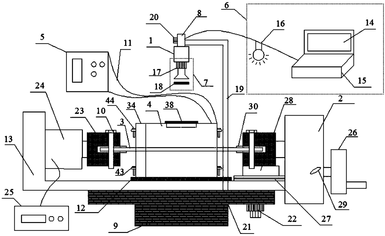
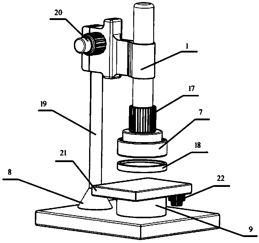
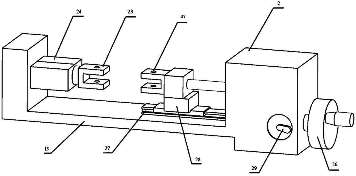
[0040] like figure 1 As shown, a ceramic matrix composite material matrix crack observation system in high temperature air environment, including: digital microscope 1, tensile test device 2, test sample 3, heating device 4, temperature controller 5, digital microscope includes a desktop main control system 6. Zoom lens 7, mirror holder 8, two-dimensional mobile platform 9, desktop main control system 6 includes display screen 14, LED lamp 16, main controller 15, display screen 14 shows the situation of material surface in real time, LED lamp 16 is used for To illuminate the surface of the test sample 3, the main controller (15) is connected with the LED lamp (16) and the zoom lens (7). The test sample 3 includes the ceramic matrix composite material, and the zoom lens 7 can be used for the ceramic matrix composite material surface. The main controller receives and st...


PUM


Abstract

The invention discloses a ceramic matrix composite material high-temperature air environment substrate crack observation system and an observation method. The system comprises a digital microscope, atension testing device, a test sample, a heating device and a temperature controller, wherein the digital microscope comprises a platform main control system, a zoom lens, a lens base and a two-dimensional moving device; the test sample is horizontally mounted on the tension testing device; the tension testing device is horizontally arranged on the two-dimensional moving device; a rectangular transparent quartz glass plate is embedded above the heating device and is horizontally placed on a thermal insulating pad of the base of the tension testing device; the zoom lens is aligned to the centerof the test sample through the transparent quartz glass plate; the heating device is connected with the temperature controller. The tension testing device, the split type micro heating device and thedigital microscope are all independent individuals and are convenient to mount and dismount, and in an atmospheric environment, matrix cracks of the ceramic matrix composite material can be conveniently observed under the action of high-temperature air and stress loads.

Description

technical field [0001] The invention relates to the technical field of material testing, in particular to an observation system for cracks in a matrix of a ceramic matrix composite material in a high-temperature air environment. Background technique [0002] Continuous fiber reinforced ceramic matrix composites have shown superiority in the aerospace field because of their high specific strength, high specific modulus, low density, and good high temperature resistance. Matrix cracking is one of the important failure modes of continuous fiber reinforced ceramic matrix composites. Obtaining the density and distribution of matrix cracks through experiments has important practical application value for predicting the failure of continuous fiber reinforced ceramic matrix composites and evaluating their static properties. [0003] Ceramic matrix composites are mainly used in high temperature air environments due to their good oxidation resistance. It is of great practical signif...

Claims


Application Information

Patent Timeline
IPC IPC(8): G01N3/18G01N21/88G01N1/44
CPCG01N1/44G01N3/18G01N21/88G01N2203/0062G01N2203/0226G01N2203/0017G01N2203/0003
Inventor 陈西辉孙志刚陈鹏宋迎东李宏宇
Owner NANJING UNIV OF AERONAUTICS & ASTRONAUTICS
Learn More