
Armor plate and manufacturing method thereof

A production method and technology of bulletproof plate, applied in the direction of armor plate structure and other directions, can solve the problems of loose ceramics, affecting the ballistic resistance performance of the bulletproof plate, etc., and achieve the effect of enhancing the adhesion strength and improving the ballistic resistance performance.

Inactive Publication Date: 2018-11-06
江苏安卡新材料科技有限公司
View PDF4 Cites 5 Cited by
  • Summary
  • Abstract
  • Description
  • Claims
  • Application Information

AI Technical Summary

Problems solved by technology

However, due to the nature of the ceramic layer itself, when a bullet breaks through the ceramic layer, the ceramic layer will gradually undergo expansionary fragmentation centered on the bullet hole, and the propagating kinetic energy will cause other ceramics around it to loosen, thus affecting the bulletproof of the bulletproof plate performance

Method used


Image

  • Armor plate and manufacturing method thereof
  • Armor plate and manufacturing method thereof

Examples


Embodiment 1

[0034] A polyethylene fiber layer with thermosetting adhesive attached thereon is provided, and multiple layers of polyethylene fiber are stacked from top to bottom. The thermosetting adhesive is a phenolic thermosetting adhesive.

[0035] Place a release film above and below the laminated multilayer polyethylene fibers, bond the surroundings of the release film with a sealant, feed the multilayer polyethylene fibers into a mold, and heat it to a set temperature. The set temperature is 132°C.

[0036] The multi-layer polyethylene fiber is laminated by four-stage lamination, wherein the curing pressure of the first stage is 6Mpa, the curing pressure of the second stage is 10Mpa, the curing pressure of the third stage is 16Mpa, and the curing pressure of the fourth stage is set to 16Mpa. The first stage of curing time is from room temperature to 90°C, the second stage of curing time is from 90°C to 128°C, the third stage of curing time is 3 hours of heat preservation and pressu...

Embodiment 2

[0039] A polyethylene fiber layer with thermosetting adhesive attached thereon is provided, and multiple layers of polyethylene fiber are stacked from top to bottom. The thermosetting adhesive is a phenolic thermosetting adhesive.

[0040] Place a release film above and below the laminated multilayer polyethylene fibers, bond the surroundings of the release film with a sealant, feed the multilayer polyethylene fibers into a mold, and heat it to a set temperature. The set temperature is 135°C.

[0041] The multi-layer polyethylene fiber is laminated by four-stage lamination, wherein the curing pressure of the first stage is 6Mpa, the curing pressure of the second stage is 10Mpa, the curing pressure of the third stage is 16Mpa, and the curing pressure of the fourth stage is set to 16Mpa. The first stage of curing time is from room temperature to 90°C, the second stage of curing time is from 90°C to 128°C, the third stage of curing time is 3 hours of heat preservation and pressu...


PUM


Abstract

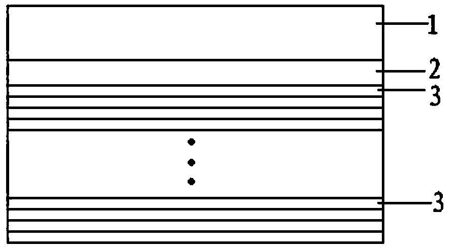
The invention provides an armor plate and a manufacturing method thereof. The armor plate comprises a ceramic layer, a connecting layer, a plurality of polyethylene fiber layers and bonding layers. The multiple polyethylene fiber layers are laminated from top to bottom. The adjacent polyethylene fiber layers are bonded through the bonding layers. Each polyethylene fiber layer is pressed and moldedthrough a laminating mode. Any polyethylene fiber layer is provided with a plurality of parallel fiber filaments arranged unidirectionally. Between everytwo adjacent polyethylene fiber layers, the fiber filaments of one polyethylene fiber layer and the fiber filaments of the other polyethylene fiber layer are arranged in an intersecting mode. The ceramic layer is combined with the multiple laminated polyethylene fiber layers through the connecting layer. The surface, making contact with the ceramic layer and the polyethylene fiber layers, of the connecting layer is the rough surface. Throughthe arrangement of the connecting layer, the bonding strength of the ceramic layer is enhanced. When the ceramic layer is broken through, left bullet holes cannot expand, propagating kinetic energy cannot cause looseness of other ceramic around, and the bulletproof property of the armor plate is remarkably improved.

Description

technical field [0001] The invention relates to the technical field of bulletproof technology, in particular to a bulletproof plate and a manufacturing method thereof. Background technique [0002] The bulletproof plate can be used as a bulletproof layer in bulletproof products such as bulletproof vests and shields. At present, the existing bulletproof plate includes a ceramic layer, and the ceramic layer is compounded on the base material layer by adhesive. However, due to the nature of the ceramic layer itself, when a bullet breaks through the ceramic layer, the ceramic layer will gradually undergo expansionary fragmentation centered on the bullet hole, and the propagating kinetic energy will cause other ceramics around it to loosen, thus affecting the bulletproof of the bulletproof plate performance. Therefore, in view of the above problems, it is necessary to propose a further solution. Contents of the invention [0003] The object of the present invention is to pro...

Claims


Application Information

Patent Timeline
IPC IPC(8): F41H5/04
Inventor 徐永红丁旭陶锴
Owner 江苏安卡新材料科技有限公司
Learn More