
Grouting device and in-hole segmented grouting method for a plurality of solution cavities

A technology of grouting device and karst cave, which is applied in the fields of tunnel rock and soil reinforcement, foundation reinforcement, and karst grouting filling. It can solve the problems of limited construction space, reduced feasibility of ground drilling and grouting construction, and discounted treatment effect of ground drilling, etc. problem, achieve the effect of reducing risk, good governance effect, and reducing trajectory error

Pending Publication Date: 2018-11-06
徐州中矿岩土技术股份有限公司
View PDF7 Cites 3 Cited by
  • Summary
  • Abstract
  • Description
  • Claims
  • Application Information

AI Technical Summary

Problems solved by technology

This method is mostly aimed at the foundation treatment process in the early stage of construction, and when the karst ground subsidence occurs in the completed buildings, due to the limited construction space, the method of vertical drilling on the ground cannot solve the problem.
[0006] The existing grouting treatment of karst cavities mostly relies on vertical exploration holes. Vertical drilling has a better effect on the treatment of single structures and lower construction costs, such as pile foundations and karst cave filling under independent foundations. In the ground treatment of linear structures such as underground pipe corridors, railways, and highways, the effect of ground drilling treatment will be greatly reduced due to the discontinuity and dispersion of karst caves.
At the same time, when the ground construction conditions are complex, and many places do not have the construction conditions of conventional drilling equipment (vertical hole drilling equipment), the construction feasibility of ground drilling and grouting will be greatly reduced. At present, there is no effective treatment method in China to complete such as subway The task of filling and grouting the karst caves encountered in linear construction projects such as tunnels, pipe galleries, etc.

Method used


Image

  • Grouting device and in-hole segmented grouting method for a plurality of solution cavities
  • Grouting device and in-hole segmented grouting method for a plurality of solution cavities
  • Grouting device and in-hole segmented grouting method for a plurality of solution cavities

Examples


Embodiment Construction

[0057] In order to solve the condition that the ground does not have conventional vertical drilling for cave grouting, the technical solution adopted in this embodiment is a shallow horizontal directional drilling grouting construction technology. It includes several construction procedures such as selection of construction land, selection of horizontal drilling rig, design of drilling trajectory, drilling data recording, detection of unfavorable geological bodies (karst caves) and grouting of karst caves in horizontal drilling areas.

[0058] Horizontal directional exploration technology is based on horizontal directional drilling technology and geophysical logging technology. Horizontal directional drilling technology is a technology that uses drilling equipment installed on the surface to drill into the formation at a small angle relative to the ground to form a pilot hole, and then expand the diameter of the pilot hole to the required size and lay the pipeline. It has trac...


PUM


Abstract

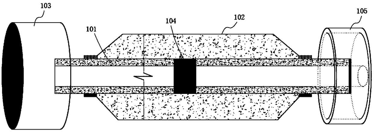
The invention discloses a grouting device and an in-hole segmented grouting method for a plurality of solution cavities. The in-hole segmented grouting method comprises the steps that s1, a drilling machine is used for drilling, and the solution cavities communicate with one another by one-time drilling; s2, the grouting device is installed at the tail end of a grouting drilling rod, and a grouting machine is sent into a specified solution cavity; s3, slurries is poured into the grouting drilling rod, a first check valve is opened by increasing grouting pressure, and a second elastic sleeve pipe of a rear grout stopping device expands to attach closely to the side wall of a drilling hole; s4, a second check valve is opened by further increasing the grouting pressure, the slurries enter thegrouting machine and a front grout stopping device, and a first elastic sleeve pipe of the front grout stopping device expands to attach closely to the side wall of the drilling hole; s5, a fourth check valve is opened by further increasing the grouting pressure, and the slurries are injected into the solution cavities; and s6, the grouting drilling rod is taken out. A construction technology method is adjusted according to the size of the solution cavities and a filling degree in a grouting process, so that an intent layer position is processed with a definite target.

Description

technical field [0001] The application relates to a grouting device and a segmented grouting method for multiple karst caves, belonging to the fields of karst grouting filling, tunnel rock and soil reinforcement, and foundation reinforcement. Background technique [0002] Karst, also known as karst, refers to the chemical and physical action of soluble rocks such as carbonate limestone, dolomite, and sulfate gypsum to produce grooves, cracks and cavities, as well as the collapse of the roof of the cavities. The general term for erosion and accumulation landform features and geological processes such as caves and depressions. [0003] The geological conditions in karst areas are generally more complicated, and the survey is difficult, and the impact and harm they produce are usually relatively large. In cities with developed karst, special geological conditions lead to strong development of karst crevices and karst caves, which can easily cause seepage liquefaction, groundwa...

Claims


Application Information

Patent Timeline
Patent Type & Authority Applications(China)
IPC IPC(8): E02D15/04E02D3/12
CPCE02D3/12E02D15/04Y02E10/20
Inventor 高盛翔史继彪何宝林李帅陈益民朱元武
Owner 徐州中矿岩土技术股份有限公司
Learn More