An antenna array device applied to 5g mobile terminals
An antenna array and mobile terminal technology, applied in the field of antenna array devices, can solve the problem of large propagation path loss in the millimeter wave frequency band
- Summary
- Abstract
- Description
- Claims
- Application Information
AI Technical Summary
Problems solved by technology
Method used
Image

Examples
Embodiment 1
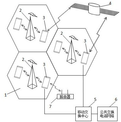
[0055] figure 1 It is the invention applied to a wireless communication network which may comprise a plurality of cells 1 comprising base stations 2 and mobile terminal devices 3 . The network may employ various communication protocols or standards for voice communication as well as data communication. The mobile terminal device 3 can communicate in the network, and at the same time, the mobile terminal device 3 can also communicate with the satellite navigation system 4 (such as GPS, Beidou, GLONASS, etc.), and the mobile terminal device 3 can communicate with the mobile switching center 5 (mobiletelephone switching center ) communication, can communicate with the Public Switched Telephone Network 6 (Public Switched Telephone Network), can also communicate with other mobile terminal devices through the Mobile Switching Center 5 or the Public Switched Telephone Network 6, and can also exchange data with the router 7, and the base station 2 can also It can communicate with the...
Embodiment 2
[0065] The difference between this embodiment and Embodiment 1 lies in the unit structure of the antenna array of the present invention.
[0066] The structure of the four-element antenna array in this embodiment is as follows: Figure 9 as shown, Figure 10 The first layer of graphics shown is the graphics layer on the upper surface of the dielectric board 39, Figure 11 The second layer of graphics shown is the graphics layer between the dielectric boards 39 and 33, Figure 12 The third layer of graphics shown is the graphics layer between the dielectric boards 33 and 34, Figure 13 The fourth layer of graphics shown is the graphics layer between the dielectric boards 34 and 40, Figure 14 The fifth layer pattern shown is the pattern layer on the lower surface of the dielectric board 40 .
[0067] The structure is the same as Figure 5 The difference in is that the Figure 5 The first rectangular metal block 310 and the second rectangular metal block 314 that constitut...
Embodiment 3
[0069] The difference between this embodiment and Embodiment 2 lies in the unit structure of the antenna array of the present invention.
[0070] The structure of the four-element antenna array in this embodiment is as follows: Figure 15 as shown, Figure 16 The first layer of graphics shown is the graphics layer on the upper surface of the dielectric board 39, Figure 17 The second layer of graphics shown is the graphics layer between the dielectric boards 39 and 33, Figure 18 The third layer of graphics shown is the graphics layer between the dielectric boards 33 and 34, Figure 19 The fourth layer of graphics shown is the graphics layer between the dielectric boards 34 and 40, Figure 20 The fifth layer pattern shown is the pattern layer on the lower surface of the dielectric board 40 .
[0071] The structure is the same as Figure 9 The difference in is that the Figure 9 The first copper clad layer 380 and the second copper clad layer 384 forming the electric dipo...
PUM
 Abstract
Description
Claims
Application Information
 - R&D
- Intellectual Property
- Life Sciences
- Materials
- Tech Scout
- Unparalleled Data Quality
- Higher Quality Content
- 60% Fewer Hallucinations
Browse by: Latest US Patents, China's latest patents, Technical Efficacy Thesaurus, Application Domain, Technology Topic, Popular Technical Reports.
© 2025 PatSnap. All rights reserved.Legal|Privacy policy|Modern Slavery Act Transparency Statement|Sitemap|About US| Contact US: help@patsnap.com