Blast furnace stockhouse arrangement

一种储藏室、供给装置的技术,应用在特别是高炉的储藏室装置,冶金炉领域,能够解决自动化储藏室复杂等问题,达到灵活适应性、便于维护、减少投资成本的效果

Active Publication Date: 2018-10-23
PAUL WURTH SA
View PDF5 Cites 2 Cited by
  • Summary
  • Abstract
  • Description
  • Claims
  • Application Information

AI Technical Summary

Problems solved by technology

In practice, modern automated storage rooms can be quite complex

Method used


Image

  • Blast furnace stockhouse arrangement
  • Blast furnace stockhouse arrangement
  • Blast furnace stockhouse arrangement

Examples


Embodiment Construction

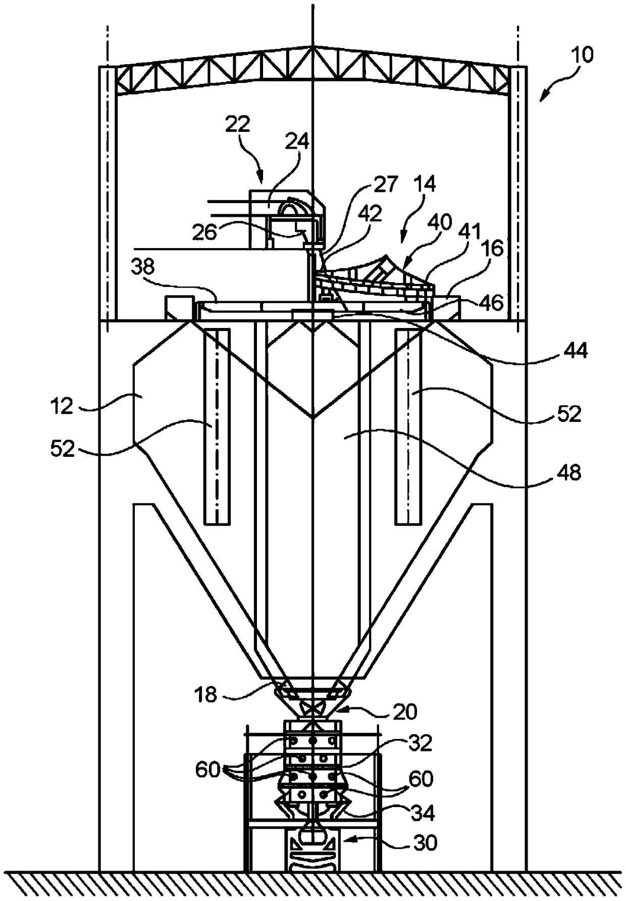
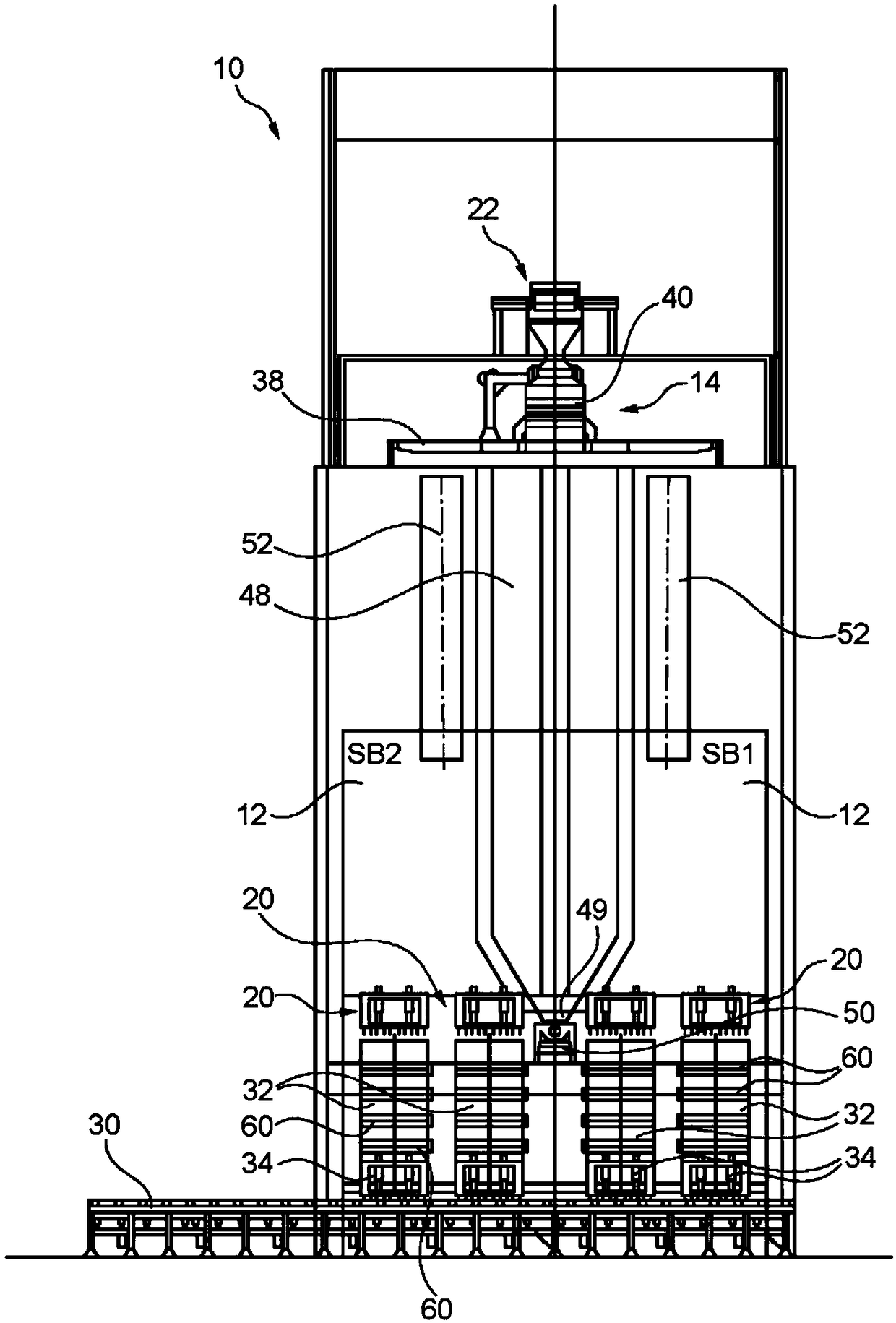
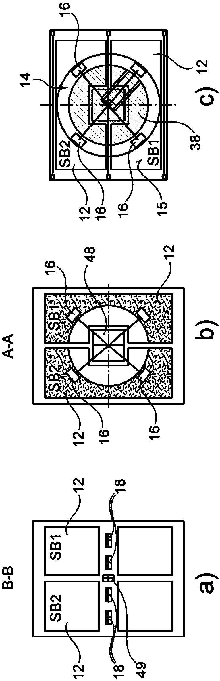
[0042] Figure 1 to Figure 3 An embodiment of the present storeroom arrangement 10 for storing, measuring and preparing charge materials for metallurgical furnaces, in particular for blast furnace workshops, is shown.

[0043] A blast furnace area with such a material storage device is commonly referred to as a storeroom; the terms "storeroom", "storehouse arrangement", "storeroom system" and "material storage facility" will be used herein without distinction.

[0044] The storage room 10 comprises a set of storage bins 12 arranged in a side-by-side manner to be filled by a material supply 14 associated therewith. The storage silo 12 has a generally funnel-like form that converges towards its lower end. The storage silo 12 has a large capacity, generally above 200 cubic meters, for example between 300 and 600 cubic meters, and even between 500 and 1000 cubic meters. The storage silo 12 is closed at its top by a cover 15 in which a supply opening 16 is arranged; and has a nar...


PUM


Abstract

A stockhouse arrangement for a metallurgical furnace comprises a set of storage bins (12) for granular material; a material feeding device (14) associated with said set of storage bins (12), the material feeding device (14) being arranged above said set of storage bins (12) and allowing to selectively fill each of the storage bins with granular material; and a raw material feed system (22) to convey raw granular material to the material feeding device (14). A respective weighing hopper (32) is arranged downstream of each storage bin (12) and comprising an outlet associated with a feeding gate(34). A charge conveying system (30) is provided for collecting and conveying material selectively discharged from the weighing hoppers through their respective feeding gate. The material feeding device (14) is configured to screen raw granular material arriving from said raw material feed system such that only material with desired granulometry is forwarded to the respective bin(s).

Description

technical field [0001] The present invention relates generally to the field of ironmaking plants, and more particularly to storeroom arrangements for metallurgical furnaces, in particular blast furnaces. Background technique [0002] As we all know, the blast furnace charging system consists of two main areas: the storage room system and the top charging equipment. The function of the storage room system is to meter, batch and distribute the raw material recipe to the top charging equipment installed above the blast furnace. The top charging equipment in turn functions to deliver blast furnace raw material to the furnace top and distributes these materials into the furnace. [0003] The storage room consists of a set of storage bins, usually fed by a feeding system with a conveyor belt. Raw material is drawn from the storage silo through a vibrating feeder and screen (optionally via a belt conveyor) into a metering hopper. The metering hopper in turn discharges the materi...

Claims


Application Information

Patent Timeline
Patent Type & Authority Applications(China)
IPC IPC(8): F27B1/20C21B5/00C21B7/20F27D3/10
CPCC21B5/008F27B1/20F27D3/10C21B7/20B07B13/14
Inventor G·庞吉里尼A·卡斯泰利亚尼
Owner PAUL WURTH SA
Why Eureka
Try Eureka