Push rod type automatic turning device for legs

An automatic flipping and push rod technology, applied in cranes and other directions, can solve the problems of reduced departure angle, difficult speed, volume and self-weight, etc., and achieve the effect of avoiding free fall, simple structure and beautiful appearance.

Active Publication Date: 2012-01-25
CHANGZHI QINGHUA MACHINERY FACTORY
View PDF0 Cites 0 Cited by
  • Summary
  • Abstract
  • Description
  • Claims
  • Application Information

AI Technical Summary

Problems solved by technology

However, the volume and dead weight of large-tonnage truck-mounted cranes (6.3 tons or more than 160KNm) are too large
When refitting the chassis of a transport vehicle, if it is arranged between the cab and the carriage, fuel tanks and storage batteries are installed on both sides of the car frame, and the width of the vehicle will exceed the limit required by the national standard; if it is arranged at the rear of the carriage , the departure angle of the vehicle decreases, which affects the passability of the vehicle
At present, most manufacturers adopt these three methods to solve the problem: (1) Change the installation position of the fuel tank and storage battery of the vehicle;
(2) The manual turning method of outrigger cylinders is adopted; however, the self-weight of the outrigger cylinders is too large, and the labor intensity is too high; at the same time, the height of the car chassis is too high, and it is difficult to achieve continuous turning within a vertical range of 180° by using manual turning methods. Realize continuous flipping in the range of 45° or 60°
This needs to increase the hydraulic valve lock, which increases the cost. At the same time, because the small oil cylinder is the power source, the outriggers turn over quickly, the speed is difficult to control, and the turning inertia is large, so the wire rope is easy to be broken.

Method used


Image

  • Push rod type automatic turning device for legs
  • Push rod type automatic turning device for legs

Examples


Embodiment Construction

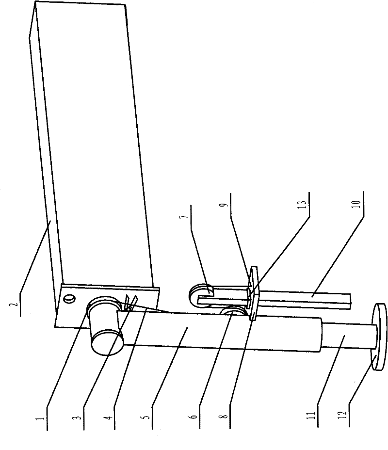
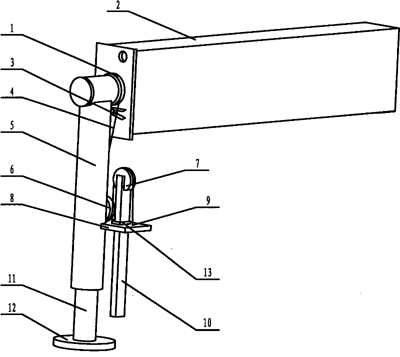
[0011] Such as figure 1 As shown, the push rod type outrigger automatic turning device includes: idler 1, hand pull beam 2, first fixed point 3 of steel wire rope, steel wire rope 4, outrigger cylinder 5, first pulley 6, second pulley 7, Guide plate 8, wire rope second fixed point 9, push rod 10, outrigger oil cylinder piston rod 11, piston rod bottom plate 12 and push rod stop plate 13, hand pull beam 2 is connected with outrigger cylinder barrel 5 through shaft, outrigger The cylinder barrel 5 is connected with the piston rod 11 of the outrigger cylinder, the piston rod bottom plate 12 is fixed at the lower end of the piston rod 11 of the outrigger cylinder, the pull beam 2 is fixedly connected with the idler 1, the idler 1 is fixed on the shaft, and the bottom of the idler 1 The first fixed point 3 of the steel wire rope is set, and the first fixed point 3 of the steel wire rope is fixed on the pull beam 2. A guide plate 8 is fixed at the middle position of the outrigger cy...


PUM


Abstract

The invention relates to a push rod type automatic turning device for legs, belonging to the technical field of turning of the legs of a lorry-mounted crane. The invention provides the push rod type automatic turning device for the legs, which is capable of realizing automatic turn of a leg cylinder within the range of 180 degrees in the vertical direction by using the retracting force of a piston rod of the leg cylinder of the lorry-mounted crane as a power. The invention has the technical scheme that the lower end of the piston rod of the leg cylinder is fixed with a piston rod bottom plate; a hand-pull beam is fixed with an idler; the idler is fixed on the shaft; a first wire rope fixating point is arranged below the idler and fixed on the hand-pull beam; the middle of the cylinder barrel of the leg cylinder is fixed with a guide plate; the guide plate is provided with a second wire rope fixating point; the middle of the guide plate is provided with a square hole; a square push rodis sheathed in the square hole of the guide plate; a stop plate of the push rod is fixed on the push rod; a second pulley is fixed on the upper end of the push rod; and a first pulley is arranged on the cylinder barrel of the leg cylinder and above the guide plate. The invention is applicable to the technical field of leg turning.

Description

technical field [0001] The invention discloses a push rod type outrigger automatic overturning device, which belongs to the technical field of overturning outriggers of truck-mounted cranes. Background technique [0002] Large-tonnage truck-mounted cranes are one of the most popular products in the truck-mounted truck market. However, the volume and dead weight of large-tonnage truck-mounted cranes (6.3 tons or more than 160KNm) are relatively large. When refitting the chassis of a transport vehicle, if it is arranged between the cab and the carriage, fuel tanks and storage batteries are installed on both sides of the car frame, and the width of the vehicle will exceed the limit required by the national standard; if it is arranged at the rear of the carriage , the departure angle of the vehicle is reduced, which affects the passability of the vehicle. Most producers adopt these three kinds of methods to solve at present: (1) change the installation position of vehicle fuel...

Claims


Application Information

Patent Timeline
Patent Type & Authority Patents(China)
IPC IPC(8): B66C23/80
Inventor 郭金龙汤志远李志青王乐有许佩霞吴庆亮覃卫文
Owner CHANGZHI QINGHUA MACHINERY FACTORY
Why Eureka
Try Eureka