
Anti-falling structure for hopper

A hopper and anti-fall technology, used in elevators, transportation and packaging, etc., can solve problems such as hidden safety hazards and free fall from a height of 7 to 8 meters, so as to avoid free fall and improve the safety factor.

Inactive Publication Date: 2014-01-08
陕西百大新能源有限公司
View PDF6 Cites 0 Cited by
  • Summary
  • Abstract
  • Description
  • Claims
  • Application Information

AI Technical Summary

Problems solved by technology

Biomass gasifiers that use pellets as raw materials can be continuously filled with augers or trays, but for large volumes of irregularly shaped block or strip-shaped scraps from furniture manufacturers, the aforementioned methods cannot be used. Way
The utility model patent with the patent number of 200620058696.4 discloses a way of lifting and lowering the hopper with a rope pulley mechanism, and using the hopper to fill from the top of the gasifier. However, this filling method has potential safety hazards: once the rope breaks, hundreds of kilograms The hopper will be in a free fall from a height of 7 to 8 meters and a dangerous situation will occur

Method used


Image

  • Anti-falling structure for hopper
  • Anti-falling structure for hopper
  • Anti-falling structure for hopper

Examples


Embodiment 1

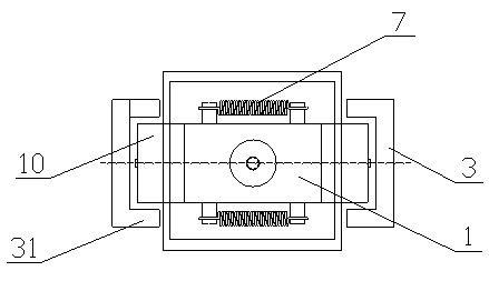
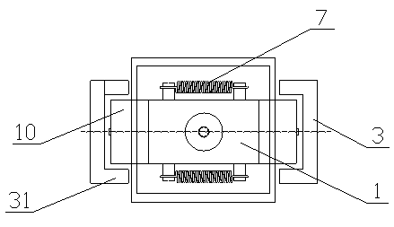
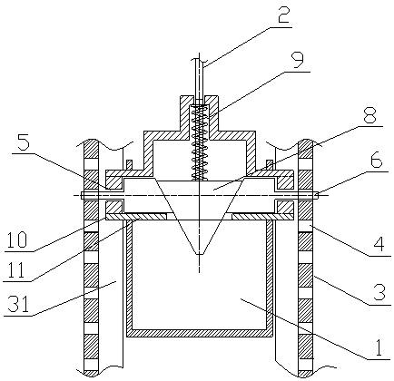
[0028] The anti-fall structure of the hopper of this embodiment includes a hopper 1 and a lifting bracket. The hopper 1 is connected with a lifting rope 2 so that the hopper 1 can be lifted or lowered under the action of the lifting rope; the lifting bracket is provided with a vertical guide 3, a guide rail 3 There are multiple locking through holes 4 at intervals; the side wall of the hopper 1 is provided with pin through holes 5 at the position corresponding to the guide rail 3, and the hopper 1 is provided with a stop pin 6 that can be inserted into the locking through hole 4, When the lifting rope 2 performs a pulling action, the stop pin 6 can be driven to exit the driving part of the locking through hole 4, and when the lifting rope 2 is broken, the stop pin 6 can be driven to pass through the pin through hole 5 and extend to the locking through hole 4 The reset section.

[0029] Specifically, there are two stop pins 6 and they are arranged opposite to each other. The drivi...

Embodiment 2

[0034] The anti-fall structure of the hopper of this embodiment includes a hopper 1 and a lifting bracket. The hopper 1 is connected with a lifting rope 2 so that the hopper 1 can be lifted or lowered under the action of the lifting rope; the lifting bracket is provided with a vertical guide 3, a guide rail 3 There are multiple locking through holes 4 at intervals; the side wall of the hopper 1 is provided with pin through holes 5 at the position corresponding to the guide rail 3, and the hopper 1 is provided with a stop pin 6 that can be inserted into the locking through hole 4, When the lifting rope 2 performs a pulling action, the stop pin 6 can be driven to retract into the driving part of the hopper 1, and when the lifting rope 2 is broken, the stop pin 6 can be driven to pass through the pin through hole 5 and extend to the stop through hole 4 Reset department.

[0035] Specifically, there are two stop pins 6 and they are arranged opposite to each other. The driving part is...


PUM


Abstract

The present invention provides a high safety factor anti-falling structure for a hopper, wherein the structure is used for a top packing type gasifier, and is provided for eliminating hidden danger caused by hopper falling due to rope breakage. The hopper anti-falling structure comprises a hopper and a pulling support. The hopper is connected with a pulling rope, such that the hopper can be lifted or lowered under the rope pulling effect. The pulling support is provided with vertical guide rails, wherein the guide rails are intervally provided with a plurality of snapping concave portions or snapping through holes. Pin passing through holes are arranged on side walls of the hopper, wherein the position of the pin passing through hole is corresponding to the guide rail. Locking pins are arranged inside the hopper, wherein the locking pins can snap into the snapping concave portions or the snapping through holes. When the rope is pulled to perform a pulling action, the locking pin can be driven to exit from the driving portion of the snapping concave portion or the snapping through-hole, and when the rope is broken, the locking pin can be driven to pass through the pin passing through hole to extend to the reposition portion of the snapping concave portion or the snapping through-hole. According to the hopper anti-falling structure of the present invention, the match of the locking pins and the guide rails is adopted, such that the hopper can be fixed on the guide rails when the pulling rope is broken so as to avoid free falling of the hopper.

Description

Technical field [0001] The invention belongs to the technical field of biomass energy utilization, and particularly relates to a hopper anti-falling structure used in a biomass gasifier. Background technique [0002] With the gradual implementation of low-carbon emission reduction policies, boilers that burn coal, diesel or wood directly in various places will gradually be phased out or renovated, thus bringing overall opportunities to the biomass gasification and oil combustion industry. Biomass gasifiers can achieve clean combustion and efficient utilization of biomass fuels, are clean, environmentally friendly, and inexpensive, and are a new trend in energy utilization. Biomass gasifiers using pellets as raw materials can be continuously filled with augers or trays, but for larger volume and irregularly shaped block or strip furniture manufacturers’ corner waste, the aforementioned cannot be used. the way. The utility model patent with the patent number 200620058696.4 discl...

Claims


Application Information

Patent Timeline
Patent Type & Authority Patents(China)
IPC IPC(8): B66B5/12
Inventor 杜海江刘光华王新强董燕萍李宗楠徐冰燕李崇实
Owner 陕西百大新能源有限公司
Learn More