Outer cover type induction vacuum annealing furnace mechanism

A vacuum annealing furnace and outer cover technology, which is applied to bell-type furnaces, furnaces, heat treatment furnaces, etc., can solve the problems of inconvenient operation, poor magnetic induction effect, and low efficiency of annealing process, so as to improve the efficiency of feeding and returning materials, The effect of eliminating the influence of heat transfer and enhancing the efficiency of electromagnetic induction

Pending Publication Date: 2018-10-19
宜兴市宇能冶金设备制造有限公司
View PDF6 Cites 0 Cited by
  • Summary
  • Abstract
  • Description
  • Claims
  • Application Information

AI Technical Summary

Problems solved by technology

[0003] 1. There is a vacuum cover between the induction coil and the workpiece, the distance between the induction coil and the workpiece is large, the resulting magnetic induction effect is poor, and the efficiency of heating the workpiece is therefore low, resulting in poor heating effect of the induction coil on the workpiece. The thermal efficiency is low, making the entire annealing process inefficient;
[0004] 2. The manufacturing process of the two-half vacuum cover is complicated, difficult to manufacture, and high in manufacturing cost. However, if the vacuum cover is designed as an integral type, the magnetic field will form a loop, which will cause serious heating of the vacuum cover and greatly reduce the annealing efficiency;
[0005] 3. The space for feeding and returning workpieces is limited, which is not easy to operate, and the efficiency of feeding and returning materials is low;
[0006] 4. The purpose of setting the induction coil outside the vacuum cover is to facilitate the sharing of induction coils at multiple stations, that is, under the condition of multiple stations, after one station is heated, the induction coil is transferred to another station to work, which saves energy. The cost of the induction coil is reduced, but the efficiency and effect of annealing are not very ideal

Method used


Image

  • Outer cover type induction vacuum annealing furnace mechanism

Examples


Embodiment Construction

[0024] The present invention will be further explained below in conjunction with the accompanying drawings and specific embodiments.

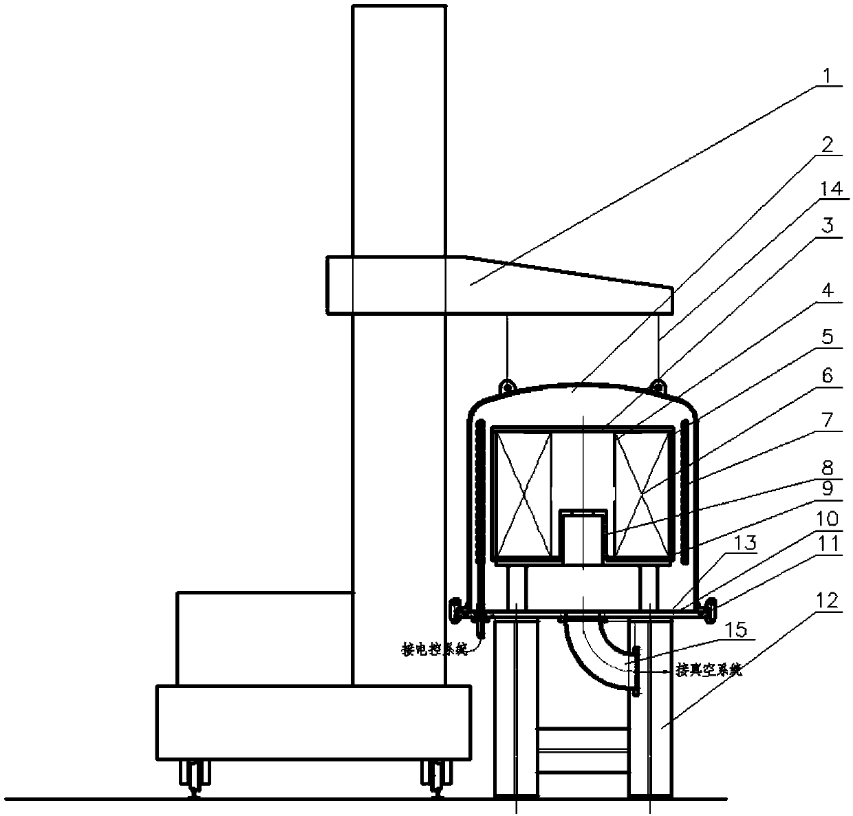
[0025] Such as figure 1 As shown, the present invention provides a cover-type induction vacuum annealing furnace mechanism, including a support 12, a base plate 10, a vacuum cover 2 positioned on the base plate 10, an induction coil 7, a vacuum tube 15 and a lifting operation trolley 1, and the vacuum cover 2 is provided with There is a hoisting base 8 for placing the workpiece 6, the hoisting base 8 is fixed on the base plate 10, the vacuum cover 2 is an integral water-cooled structure and the bottom is connected to the base plate 10, the base plate 10 is fixed on the bracket 12, and the induction coil 7 is fixed on the base plate 10 and located in the vacuum cover 2, the lifting operation trolley 1 is used to hoist the vacuum cover 2 and lift it from the bottom plate 10 and lift the workpiece 6 in and out. The vacuum cover 2 is respectively p...


PUM


Abstract

The invention discloses an outer cover type induction vacuum annealing furnace mechanism. The mechanism comprises a support, a bottom plate, a vacuum cover, an induction coil, a vacuumizing pipe and alifting operation trolley, wherein the vacuum cover is located on the bottom plate; a lifting base used for placing a workpiece is arranged in the vacuum cover, the vacuum cover is of an integral structure and the bottom of the vacuum cover is connected to the bottom plate, and the bottom plate is fixed on the support; and the induction coil is fixed on the bottom plate and is positioned in the vacuum cover, and the lifting operation trolley is used for lifting the vacuum cover away from the bottom plate and lifting the workpiece into and out of the bottom plate. According to the outer covertype induction vacuum annealing furnace mechanism, the vacuum cover adopts an outer cover structure design, so that the feeding and material returning are greatly facilitated; and the induction coil is positioned inside the vacuum cover, the distance between the induction coil and the workpiece is closer, and the heat transfer influence of the vacuum cover on the induction coil is eliminated, so that the heat efficiency of the workpiece is greatly improved.

Description

technical field [0001] The invention relates to the technical field of annealing furnaces, in particular to an outer cover type induction vacuum annealing furnace mechanism. Background technique [0002] The vacuum cover of the existing vacuum annealing furnace is fixed on the annealing furnace. Due to the limitation of its layout structure and the convenience of feeding and unloading materials, the induction coil for heating the workpiece is arranged outside the vacuum cover. In this way, in order to avoid electromagnetic induction, The vacuum cover is usually designed in two halves, so that, in the actual annealing process, there are the following defects: [0003] 1. There is a vacuum cover between the induction coil and the workpiece, the distance between the induction coil and the workpiece is large, the resulting magnetic induction effect is poor, and the efficiency of heating the workpiece is therefore low, resulting in poor heating effect of the induction coil on the...

Claims


Application Information

Patent Timeline
Patent Type & Authority Applications(China)
IPC IPC(8): C21D9/663C21D9/665C21D9/673C21D9/677
CPCC21D9/663C21D9/665C21D9/673C21D9/677
Inventor 汤宁毅金俊王政
Owner 宜兴市宇能冶金设备制造有限公司
Why Eureka
Try Eureka