System for generating medium-pressure high-temperature steam through printing and dyeing wastewater afterheat

A technology for printing and dyeing wastewater and high-temperature steam, applied in the field of high-temperature steam systems, can solve the problems of blockage of sewage sources, less installation of waste heat recovery, and low enthusiasm for heat energy recovery, so as to improve clogging and corrosion, reduce environmental pollution, and improve economic benefits. Effect

Inactive Publication Date: 2018-10-12
山东润中环境技术发展有限公司
View PDF5 Cites 5 Cited by
  • Summary
  • Abstract
  • Description
  • Claims
  • Application Information

AI Technical Summary

Problems solved by technology

However, the existing printing and dyeing wastewater and waste heat recovery technology of sewage source heat pump technology mainly have the following two problems: 1. The sewage source heat pump technology is mostly used for urban sewage treatment, the project scale is relatively large, and the application technology is relatively simple and mature. The application of sewage is less and the general plate heat exchanger is easy to cause blockage of sewage source
2. The existing technology mainly uses the heat pump to heat the treated river water required in the printing and dyeing process to about 60°C. In engineering applications, many printing and dyeing enterprises cannot continue to produce and use hot water in time due to the limited discharge of printing and dyeing sewage. Due to factors such as the initial investment in equipment and the layout of recovery devices, the enthusiasm for heat recovery is not high, especially for small and medium-sized printing and dyeing enterprises, which rarely install waste heat recovery equipment
Therefore, the recovery and utilization efficiency of low-grade heat energy needs to be improved, thereby reducing the large amount of steam energy consumption in the printing and dyeing process

Method used


Image

  • System for generating medium-pressure high-temperature steam through printing and dyeing wastewater afterheat
  • System for generating medium-pressure high-temperature steam through printing and dyeing wastewater afterheat
  • System for generating medium-pressure high-temperature steam through printing and dyeing wastewater afterheat

Examples


Embodiment Construction

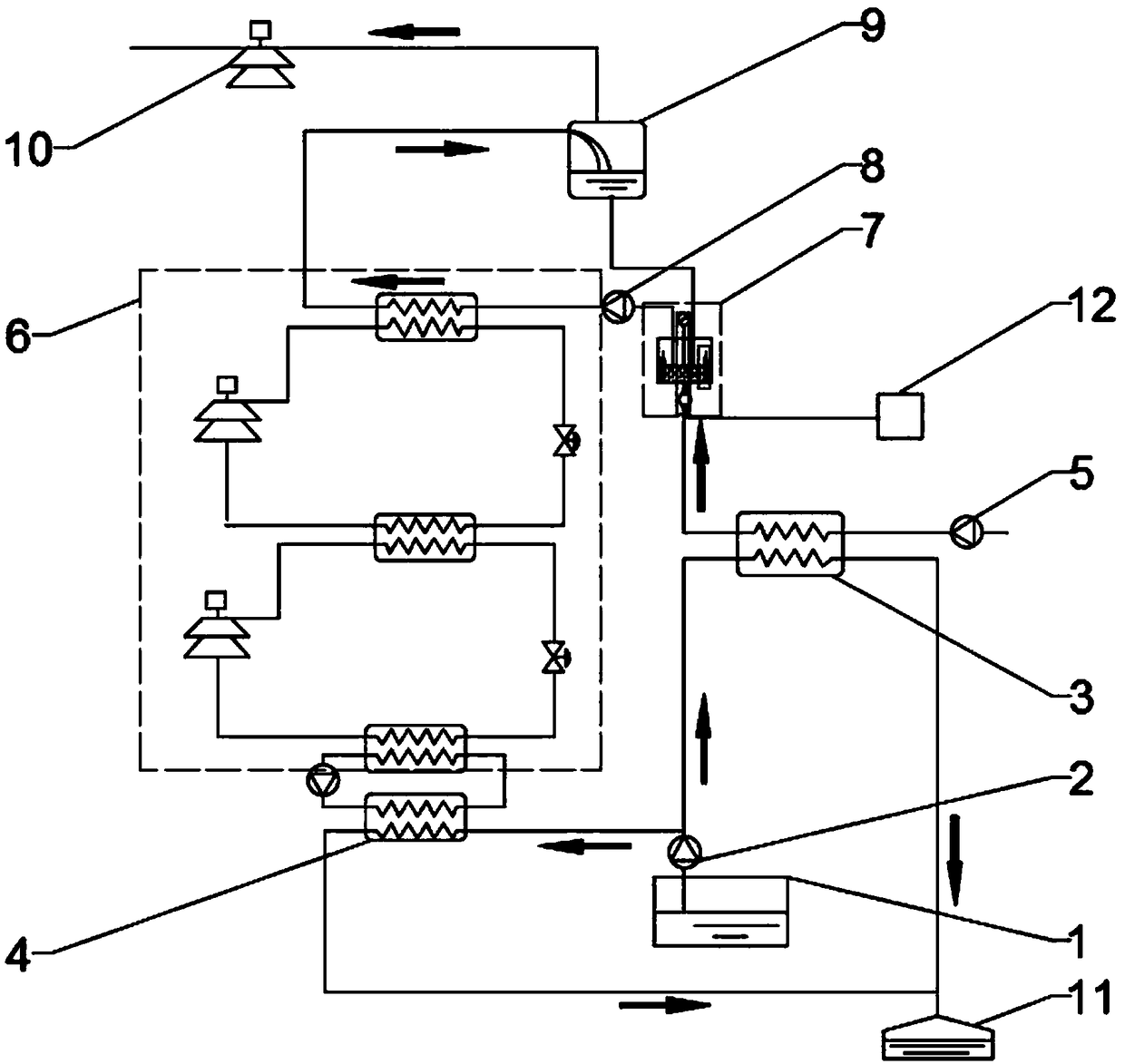
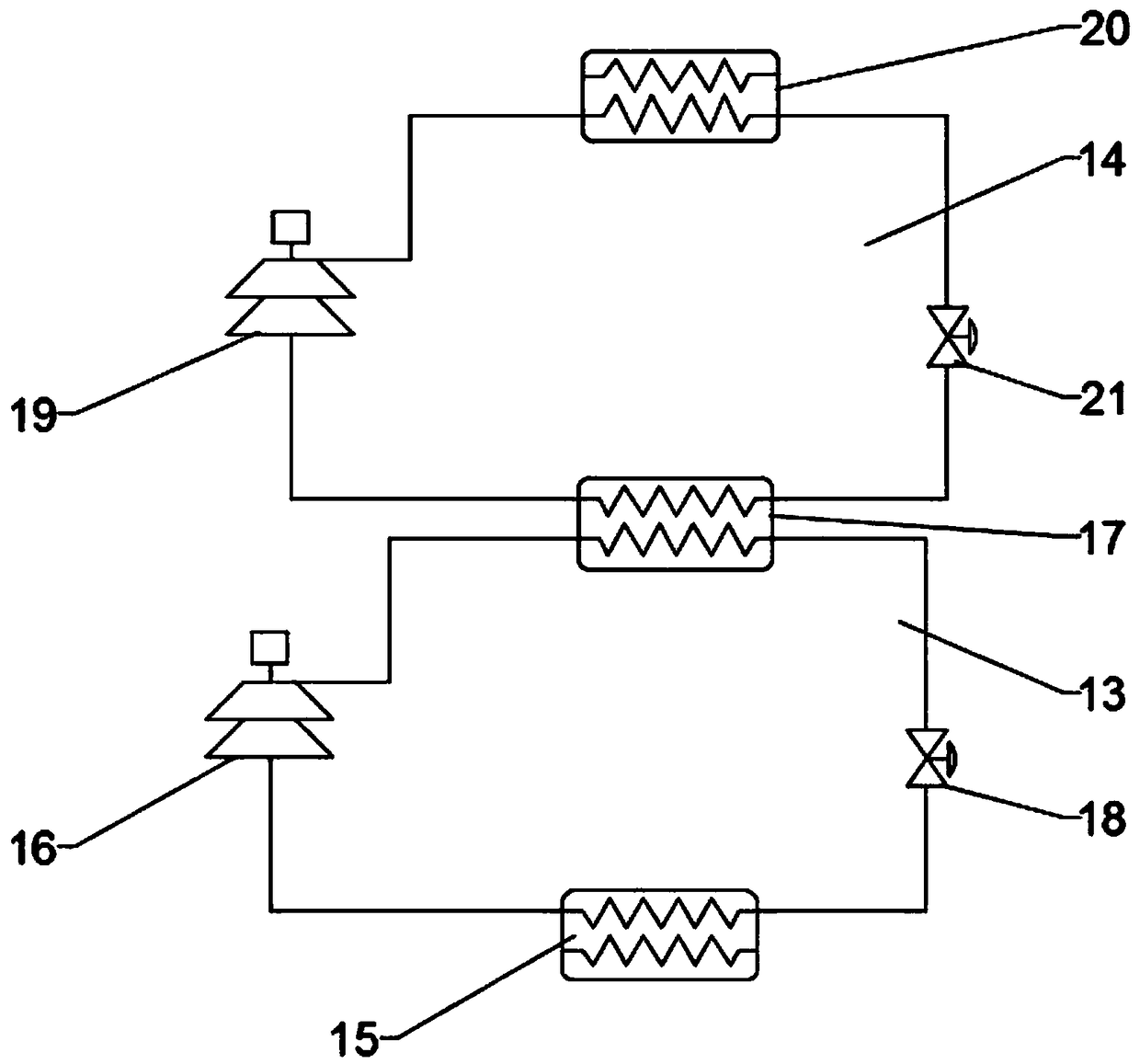
[0018] Such as figure 1 , using the residual heat of printing and dyeing wastewater to generate medium-pressure high-temperature steam system, the wastewater from the printing and dyeing wastewater pool 1 is divided into the first water flow and the second water flow through the anti-clogging centrifugal pump 2, and the first water flow enters the first shell-and-tube heat exchanger and The water input by the cold water delivery pump 5 performs heat exchange, and the cooled waste water after the exchange is discharged into the cooling sewage discharge pool 11, and the heated hot water after the exchange is mixed with the hot water 12 obtained from other processes and enters the high-temperature hot water recovery system 7. The hot water delivery pump 8 enters the high-temperature heat pump unit 14 of the cascade heat pump unit 6. After the second water flows through the second shell-and-tube heat exchanger 4 for heat exchange, the cooled waste water is discharged into the cooli...


PUM


Abstract

The invention discloses a system for generating medium-pressure high-temperature steam through printing and dyeing wastewater afterheat. The system comprises a printing and dyeing wastewater pool, a centrifugal pump, a first tube-shell heat exchanger, a second tube-shell heat exchanger, a cold water conveying pump, a cascade heat pump unit, a high-temperature hot water recycling system, a hot water conveying pump, a flash tank, a steam compressor, a cooled sewage discharging pool and a plurality of pipelines. By using a large amount of afterheat in printing and dyeing wastewater and combiningwith afterheat of multiple equipment in the process, the medium-pressure high-temperature steam which can be reused is generated, reduction of the environmental pollution is facilitated, the cost is reduced, and the economic benefits are improved. By using the tube-shell heat exchangers, blockage and corrosion of the printing and dyeing wastewater to a heat pump are reduced, and meanwhile a tube-shell heat exchanger system can effectively control the flow and the temperature of the tube-shell heat exchangers, so that the stability of a heat pump system is further improved.

Description

technical field [0001] The invention relates to the field of waste heat recovery in printing and dyeing process, in particular to a system for generating medium-pressure high-temperature steam by using waste heat in printing and dyeing. Background technique [0002] Energy shortage, environmental pollution and ecological damage are the three major problems in the world, and they are common problems that urgently need to be solved in economic and social development. At present, the rapid development of the textile industry in the industry shows that my country has mastered excellent printing and dyeing technology and has become the world's largest textile exporting country. However, the printing and dyeing industry itself is a wet and thermal processing industry. The three high labels of "high energy consumption, high water consumption, and high pollution" are unavoidable problems for printing and dyeing factories. [0003] Printing and dyeing factories consume a lot of heat...

Claims


Application Information

Patent Timeline
Patent Type & Authority Applications(China)
IPC IPC(8): F22B1/16F25B30/02F25B30/06
CPCF22B1/16F25B30/02F25B30/06
Inventor 许津津许子娴冯国增袁伶黄粱钦冯慧敏翟羽佳
Owner 山东润中环境技术发展有限公司
Why Eureka
Try Eureka